
Process for the automatic determination of speed limitations on a road and an associated system

a technology of automatic determination and associated system, which is applied in the field of automatic determination of speed limitations on roads and associated systems, can solve the problem of not being able to provide a limped home mode, and achieve the effect of removing the risk of confusion

Active Publication Date: 2013-04-23
VALEO VISION SA
View PDF15 Cites 29 Cited by
  • Summary
  • Abstract
  • Description
  • Claims
  • Application Information

AI Technical Summary

Benefits of technology

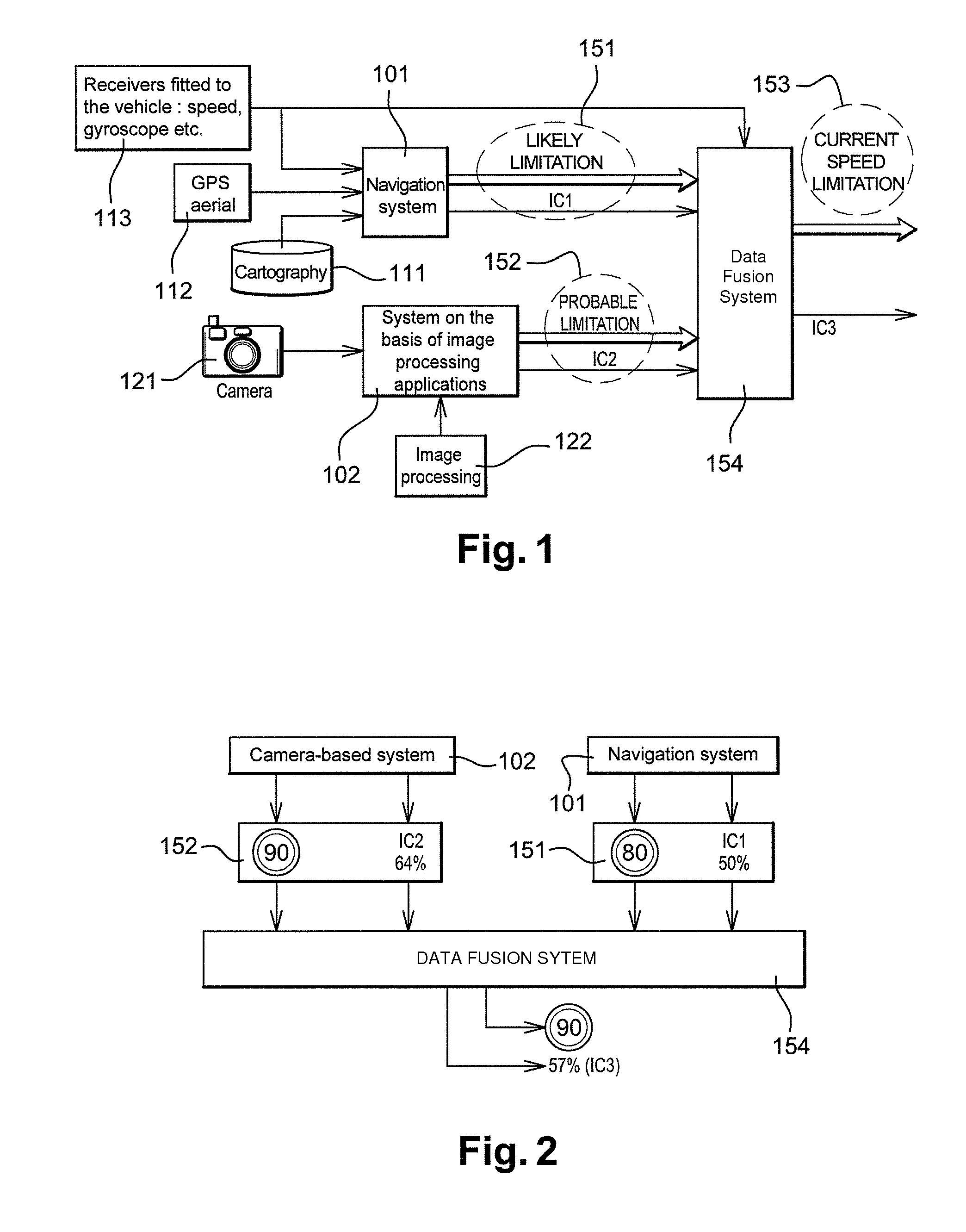
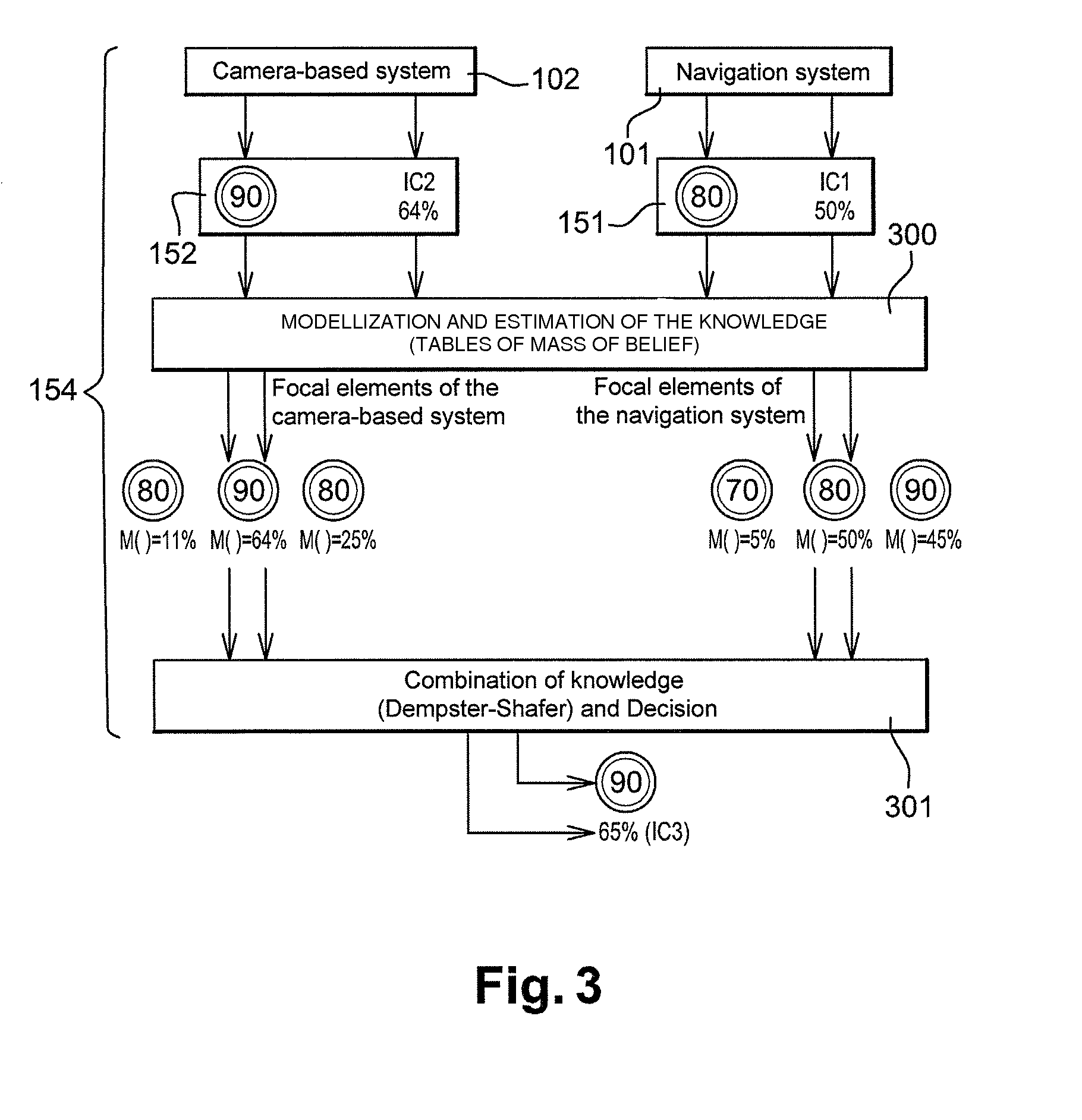
[0019]The object of the present invention proposes a solution to the problems outlined above. In a general manner, in order to determine a given speed limit on a particular road, the invention proposes the combination of the two systems mentioned above, namely the navigation system and the system combining a camera and image processing applications, by proposing to do the fusion these two sources of information. In this way, a much more reliable system for the determination of current speed limits is obtained than the systems of the prior art. In particular, this eliminates the risks of confusion attributable to incorrect information or an incorrect interpretation of this information. In this way, one particular embodiment of the present invention proposes the advantage of having a limped home mode in the event that one of the two systems should fail, with the system continuing to operate on the basis of the other system. This possibility of a limped home mode is not available in the current state of the art.

Problems solved by technology

This possibility of a limped home mode is not available in the current state of the art.

Method used


Image

  • Process for the automatic determination of speed limitations on a road and an associated system
  • Process for the automatic determination of speed limitations on a road and an associated system
  • Process for the automatic determination of speed limitations on a road and an associated system

Examples


Embodiment Construction

[0083]Unless otherwise indicated, the different elements appearing on the figures have retained the same reference numbers.

[0084]FIG. 1 shows in a schematic form the different elements of a typical embodiment of the process in accordance with the invention fitted to a motor vehicle, enabling a speed limitation (commonly known as a speed limit) 153 to be obtained on a road being used, or about to be used, by a motor vehicle. The vehicle in question contains a first system 101, known as the navigation system, enabling in particular an authorized speed to be estimated at a given point and making use, in particular of cartography details 111 and a GPS aerial 112 placed on the vehicle and able to receive precise location details. In the embodiment shown, the first system 101 also has a number of receivers 113 fitted to the vehicle in question, of the speed recorder, gyroscope etc. These different receivers 113 are able to provide different information, allowing in particular the consiste...


PUM


Abstract

An automatic process is provided for automatically determining a current speed limitation on a road being used by a motor vehicle, in which by means of a first system, making use in particular of a GPS aerial and cartographical details, a first set of information is established, in which at least one likely speed limitation is associated with a confidence index; by means of a second system, involving the use of a camera and image processing applications capable of identifying roadside speed limitation panels, a second set of information is established comprising at least one probable speed limitation, wherein the basis of the first and second sets of information, the current speed limitation is determined along the road in question.

Description

CROSS-REFERENCE TO RELATED APPLICATIONS[0001]This application claims priority to French Application No. 0705299 filed Jul. 20, 2007, which application is incorporated herein by reference and made a part hereof.BACKGROUND OF THE INVENTION[0002]1. Field of the Invention[0003]The object of the present invention relates to a process for the determination of speed limits on a road used by a motor vehicle and a process for the operation of this system. The aim of the present invention is essentially to propose a solution whereby, under all conditions, information relating to a speed limitation to be applied to a road in use, or on the point of being used, by a motor vehicle. The information collected in this manner can then be used in the different applications with which the vehicle in question is equipped. Notably, but not in a limiting manner, information relating to a speed limitation can be used within a system aimed at helping to indicate explicitly the maximum authorized speed limi...

Claims


Application Information

Patent Timeline
Patent Type & Authority Patents(United States)
IPC IPC(8): G06K9/00G06G7/76
CPCG08G1/096716G08G1/096783G08G1/096791G08G1/09623G08G1/09626
Inventor BRADAI, BENAZOUZHERBIN-SAHLER, ANNELAUFFENBURGER, JEAN-PHILIPPEBASSET, MICHEL
Owner VALEO VISION SA
Learn More