Power line carrier (PLC) communication of standby generator status

a power line carrier and status communication technology, applied in the field of system and method for monitoring the status of a standby generator, can solve problems such as unwoidly steps

Inactive Publication Date: 2013-02-12
BRIGGS & STRATTON LLC
View PDF10 Cites 13 Cited by
  • Summary
  • Abstract
  • Description
  • Claims
  • Application Information

AI Technical Summary

Problems solved by technology

In bad weather conditions, such steps are not desirable.

Method used


Image

  • Power line carrier (PLC) communication of standby generator status
  • Power line carrier (PLC) communication of standby generator status
  • Power line carrier (PLC) communication of standby generator status

Examples


Embodiment Construction

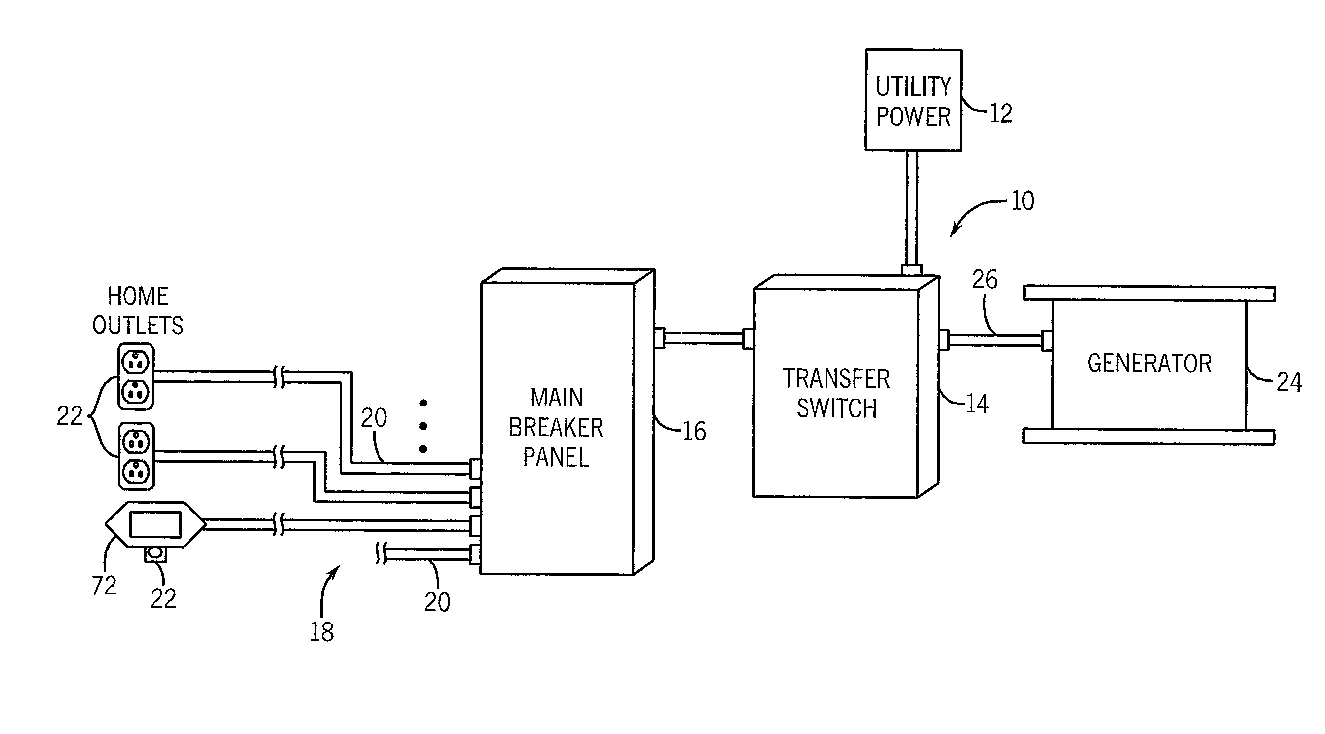
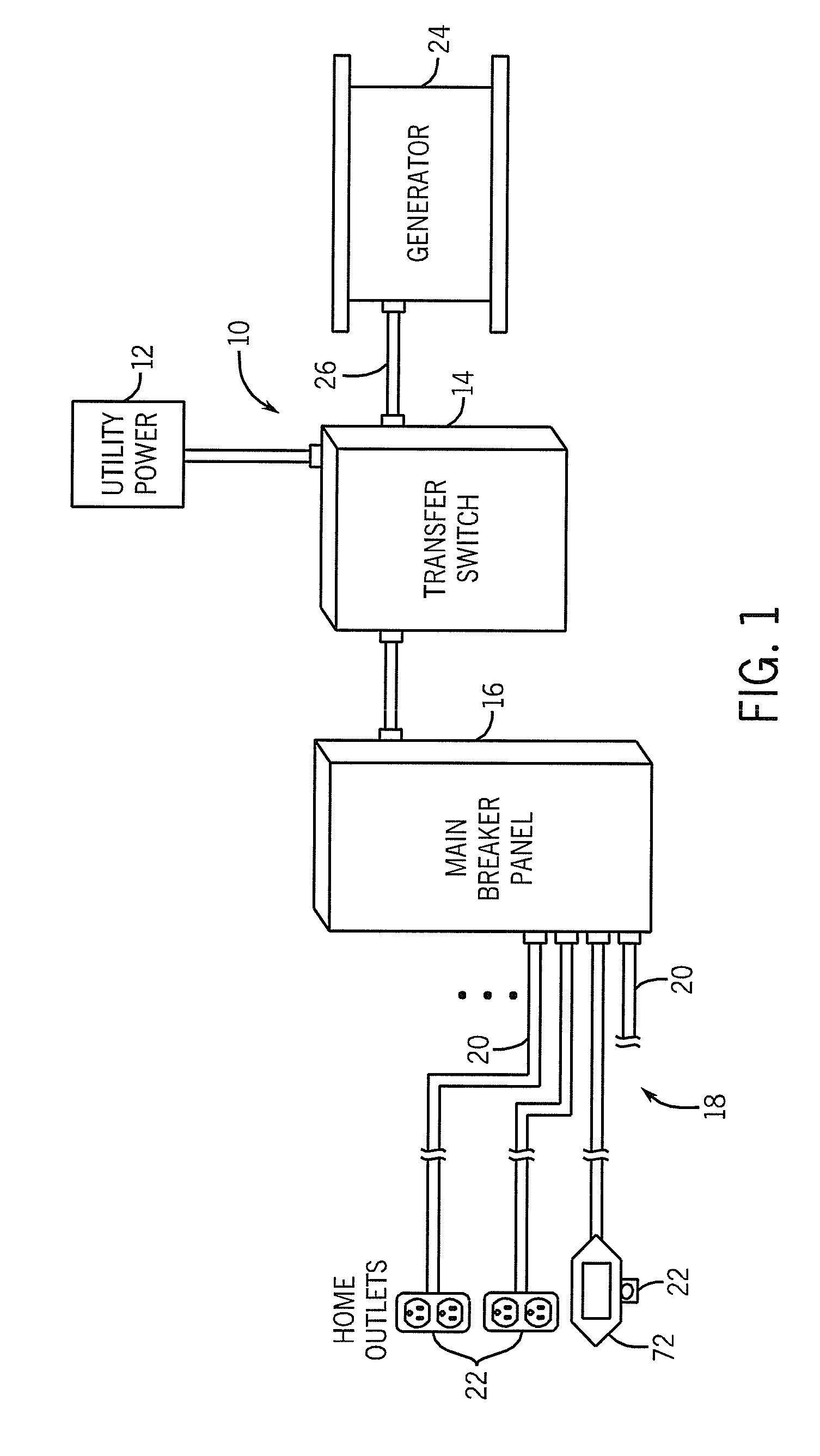
[0018]FIG. 1 depicts a load management system 10 used in a residence. The load management system 10 includes a connection to a main power supply 12. The power supply 12 is fed into a transfer switch 14. The transfer switch 14 carries out a series of functions, as will be described below, and can also be referred to as a load management controller.

[0019]The transfer switch 14 feeds electrical power to a main breaker panel 16 for the residence. The main breaker panel 16 in turn is connected to the power distribution network 18 of the home. The power distribution network 18 includes a series of individual circuits 20. In the embodiment shown in FIG. 1, each of the electrical circuits 20 includes one or more electrical outlets 22. The electrical outlets 22 can receive a plug from any one of a plurality of different electrical loads positioned within the home. The power distribution network 18 is schematically illustrated in FIG. 1 and it should be understood that the power distribution ...


PUM


Abstract

A method and system for remotely monitoring the status of a standby generator. The system includes a PLC transmitter in communication with the control unit for the generator. The PLC transmitter receives error codes from the control unit of the generator and transmits encoded error codes over the power distribution network in a home using a PLC frequency. A remote status display device can be connected to the power distribution network in the home at any convenient location. The remote status display device includes a PLC receiver that decodes the error codes. The decoded error codes are displayed on a display of the remote status display device for viewing by the home occupant at a location remote from the standby generator.

Description

BACKGROUND OF THE INVENTION[0001]The present disclosure generally relates to a system and method for monitoring the status of a standby generator. More specifically, the present disclosure relates to a method and system for remotely monitoring the status of a standby generator through a display device connected to the power distribution network of a home through any one of a plurality of electrical outlets.[0002]When there is a residential power outage, backup power may be provided to a residence by a standby generator. In some cases, the standby generator is started automatically after detection of the power outage. A standby generator that is started automatically usually requires an automatic transfer switch to connect electrical loads within the residence to the generator rather than to the power supply in the home. A combination of a standby generator and an automatic transfer switch is generally installed in the residence by trained personnel.[0003]Since standby generators may...

Claims


Application Information

Patent Timeline
Patent Type & Authority Patents(United States)
IPC IPC(8): G08B21/00
CPCH04B3/54H04B2203/5458
Inventor GILPATRICK, RICHARD J.
Owner BRIGGS & STRATTON LLC
Why Eureka
Try Eureka