
Method for operating a motorized roller shade

a motorized and roller shade technology, applied in the direction of motor/generator/converter stopper, dynamo-electric converter control, movable grille, etc., can solve the problems of high self-generated noise, inadequate battery life, and battery-powered systems

Inactive Publication Date: 2013-02-05
THE WATT STOPPER
View PDF97 Cites 91 Cited by
  • Summary
  • Abstract
  • Description
  • Claims
  • Application Information

AI Technical Summary

Benefits of technology

Enhances battery life by 20%, reduces noise, and provides flexible installation options while maintaining efficient operation and manual control capabilities.

Problems solved by technology

Unfortunately, these battery-powered systems suffer from many drawbacks, including, for example, high levels of self-generated noise, inadequate battery life, inadequate or nonexistent counterbalancing capability, inadequate or nonexistent manual operation capability, inconvenient installation requirements, and the like.

Method used


Image

  • Method for operating a motorized roller shade
  • Method for operating a motorized roller shade
  • Method for operating a motorized roller shade

Examples


Embodiment Construction

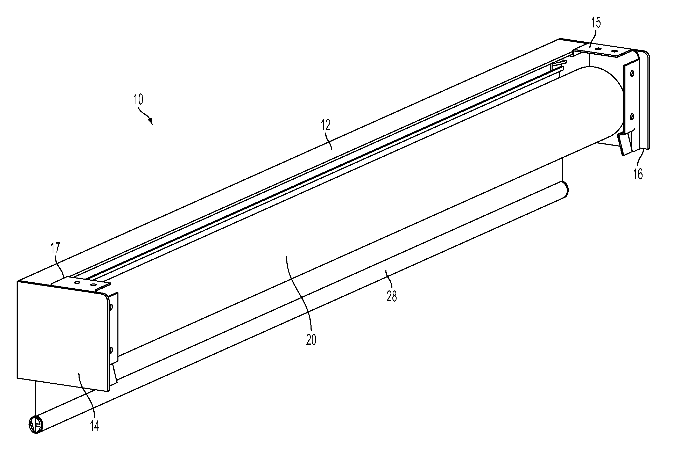
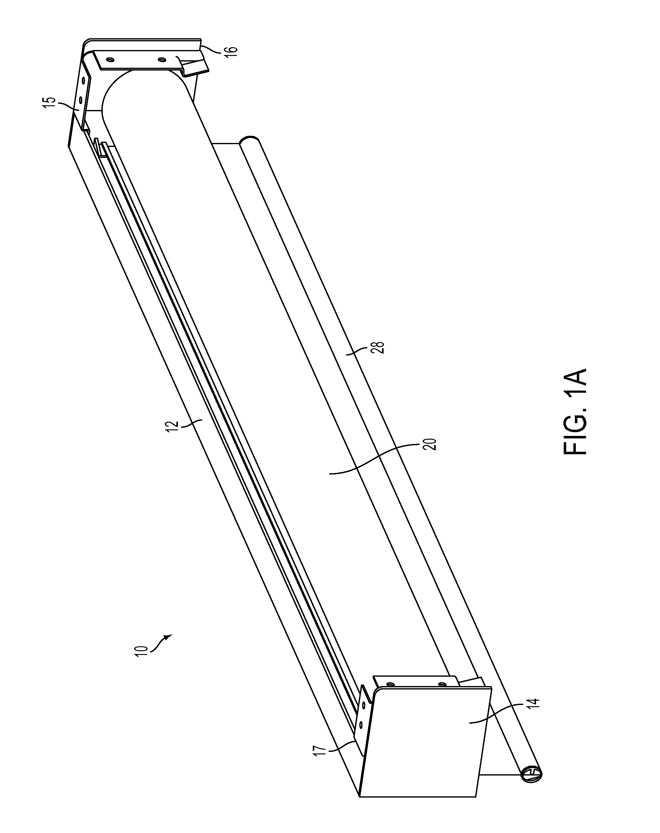
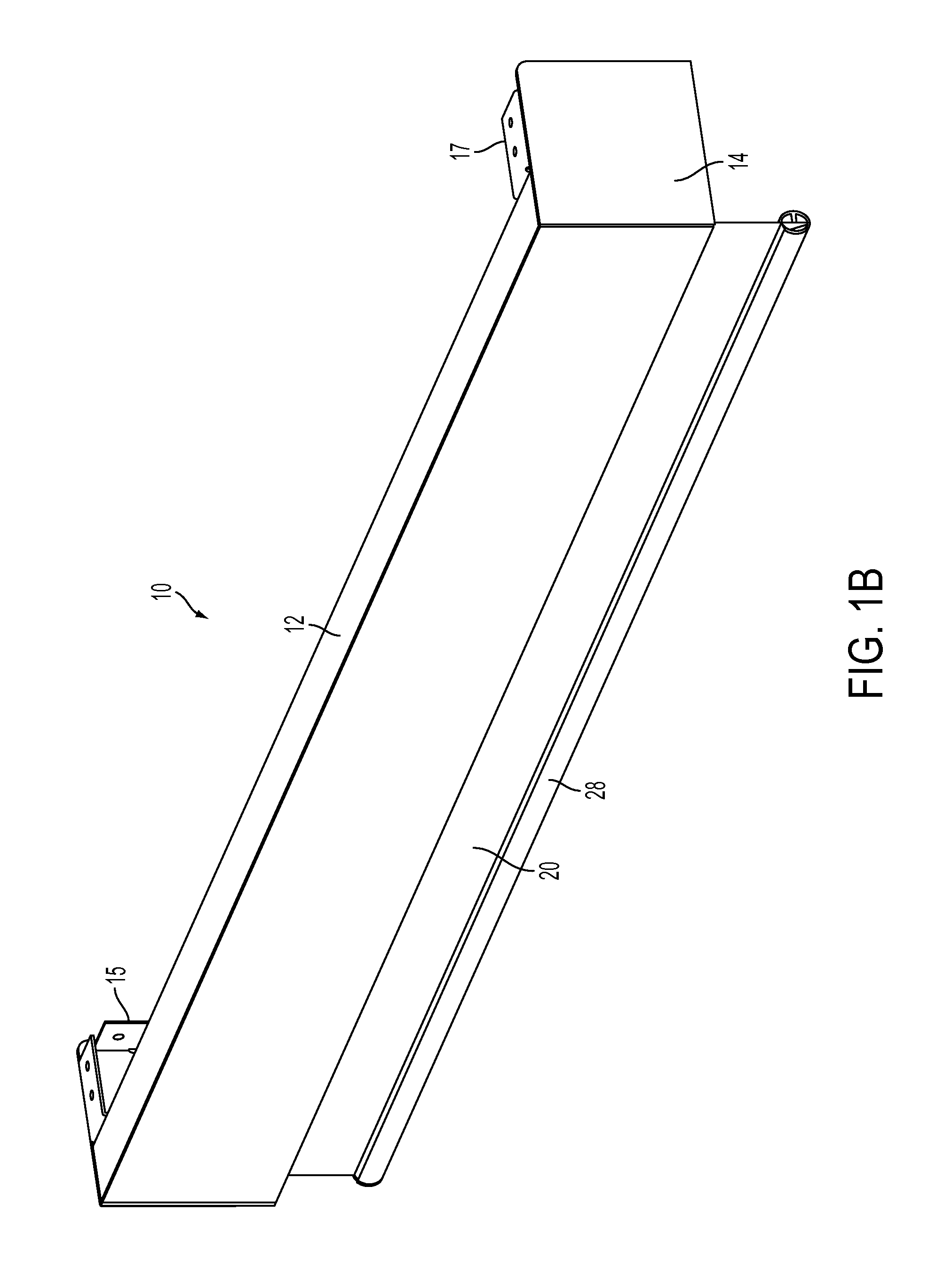
[0031]The invention will now be described with reference to the drawing figures, in which like reference numerals refer to like parts throughout. The term “shade” as used herein describes any flexible material, such as a shade, a curtain, a screen, etc., that can be deployed from, and retrieved onto, a storage tube.

[0032]Embodiments of the present invention provide a remote controlled motorized roller shade in which the batteries, DC gear motor, control circuitry are entirely contained within a shade tube that is supported by bearings. Two support shafts are attached to respective mounting brackets, and the bearings rotatably couple the shade tube to each support shaft. The output shaft of the DC gear motor is fixed to one of the support shafts, while the DC gear motor housing is mechanically coupled to the shade tube. Accordingly, operation of the DC gear motor causes the motor housing to rotate about the fixed DC gear motor output shaft, which causes the shade tube to rotate about...


PUM


Abstract

The present invention advantageously provides methods for manually and / or remotely controlling a motorized roller shade that includes a shade attached to a shade tube, a DC gear motor disposed within the shade tube and a microcontroller. One method includes detecting a manual movement of the shade using a sensor, determining a displacement associated with the manual movement, and, if the displacement is less than a maximum displacement, moving the shade to a different position by energizing the DC gear motor to rotate the shade tube. Another method includes receiving a command from a remote control, and moving the shade to a position associated with the command by energizing the DC gear motor to rotate the shade tube.

Description

FIELD OF THE INVENTION[0001]The present invention relates to a motorized shade. Specifically, the present invention relates to a high-efficiency roller shade.BACKGROUND OF THE INVENTION[0002]One ubiquitous form of window treatment is the roller shade. A common window covering during the 19th century, a roller shade is simply a rectangular panel of fabric, or other material, that is attached to a cylindrical, rotating tube. The shade tube is mounted near the header of the window such that the shade rolls up upon itself as the shade tube rotates in one direction, and rolls down to cover the a desired portion of the window when the shade tube is rotated in the opposite direction.[0003]A control system, mounted at one end of the shade tube, can secure the shade at one or more positions along the extent of its travel, regardless of the direction of rotation of the shade tube. Simple mechanical control systems include ratchet-and-pawl mechanisms, friction brakes, clutches, etc. To roll th...

Claims


Application Information

Patent Timeline
Patent Type & Authority Patents(United States)
IPC IPC(8): H02P1/00H02P3/00H02P5/00H02P7/00
CPCE06B9/42E06B9/72G08C17/02G08C23/04E06B2009/6818E06B2009/6845E06B2009/6872E06B2009/6881G08C2201/50G08C2201/51E06B9/68E06B9/74A47H5/02E06B2009/6809
Inventor MULLET, WILLIS JAYBRUNK, DARRIN W.WYSOCZYNSKI, CHRISTOPHER LEEASBURY, HARRY EDWARDHAND, RICHARD SCOTTRODRIGUEZ, YANBRUCKNER, BENJAMIN ANTHONY
Owner THE WATT STOPPER
Learn More