X-ray tube and method for examining a target by scanning with an electron beam

a technology of electron beam and x-ray tube, which is applied in the direction of x-ray tube, discharge tube incandescent screen, cathode ray concentrating/focusing/directing, etc., to achieve the effect of facilitating fault diagnosis in the case of malfunction

Active Publication Date: 2013-01-29
COMET AG
View PDF23 Cites 28 Cited by
  • Summary
  • Abstract
  • Description
  • Claims
  • Application Information

AI Technical Summary

Benefits of technology

[0006]An aspect of the present invention is to provide an X-ray tube in which fault diagnosis in the case of malfunctions is made easier and to provide a method for examining a target.
[0011]Fault diagnosis in X-ray tubes is greatly simplified in this way. In particular, time-consuming and therefore costly work steps which result if the X-ray tube is opened to examine the target, although a problem that has occurred is not due to the target being worn, are avoided. On the basis of the teaching according to the invention, it can be recognized whether the target is worn without having to open the X-ray tube.
[0012]A particular advantage of the teaching according to the invention is that some of the components and component groups needed to implement it are present in an X-ray tube in any event. This is true in particular of the means for directing an electron beam at the target, which generally include a deflector by means of which the electron beam can be deflected in two dimensions in such a way that it can be directed at different spatial points of the target. Also present where appropriate is a measurement device for measuring the target current at suitable X-ray tubes, such as is known for example from DE 103 52 334 A1. The outlay on equipment for the implementation of the teaching according to the invention is thus relatively small.
[0016]An advantageous development of the teaching according to the invention provides that the evaluation device includes a memory for storing target current / scanning site values allocated to each other. With this embodiment it is possible in particular to access the stored values and deduce from them more precise information as to whether and if appropriate at which points the target is worn away. In this way, the state of wear of the target in terms of space can be evaluated in a more differentiated way, in order for example, when the target is worn away at one point, to direct the electron beam at another point on the target when the X-ray tube is operating to produce X-radiation.
[0017]In particular if an operator of the X-ray tube is to judge whether the target is worn away or not, it is expedient to represent graphically the results of the measurement of the target current at the different scanning sites. To this end, an advantageous development of the teaching according to the invention provides for a display device connected to the evaluation device for the graphic representation of target current / scanning site values allocated to each other. In particular it is possible according to the invention to represent the target current / scanning site values in a triaxial coordinates system in which for example the current intensity of the target current over the areal extent of the target in X- and Y-directions is plotted on the Z-axis. A suitable graph can for example and in particular be represented in the manner of a pseudo-3D representation on the display device, with the result that it can easily be recognized whether and at what points the target is worn away.
[0019]Another advantageous development of the teaching according to the invention provides that the control device can be switched between an operating mode, in which the electron beam is directed essentially location-stable at the target in order to produce X-radiation, and an examination mode, in which the electron beam scans the target. The control device can be switched manually between the operating mode and the examination mode in this embodiment. However, as the scanning of the target by means of the electron beam and the measurement of the current intensity, allocated to the respective scanning site, of the target current can be carried out very quickly, it is also possible to automatically switch from the operating mode into the examination mode and back, for example at predefined time intervals or each time before an X-ray image sequence is recorded. If it is established in the examination mode that the target is worn away, a corresponding visual or acoustic warning signal can be emitted. In this way, the operational reliability of the X-ray tube is further increased, because there is automatic recognition that the target is worn and thus avoidance of an operation of the X-ray tube with a worn target.

Problems solved by technology

If the target layer is damaged, the electron current strikes the beryllium support layer.

Method used


Image

  • X-ray tube and method for examining a target by scanning with an electron beam
  • X-ray tube and method for examining a target by scanning with an electron beam
  • X-ray tube and method for examining a target by scanning with an electron beam

Examples


Embodiment Construction

[0029]In the figures, identical or corresponding components are given the same reference numbers. The drawing represents only those component groups of an X-ray tube which are needed to explain the teaching according to the invention. As the basic structure of an X-ray tube is generally known to a person skilled in the art, the component groups necessary in practice, for example a casing that can be evacuated in which the components of the X-ray tube are housed, are not shown in the drawing. Nor are they explained in more detail here.

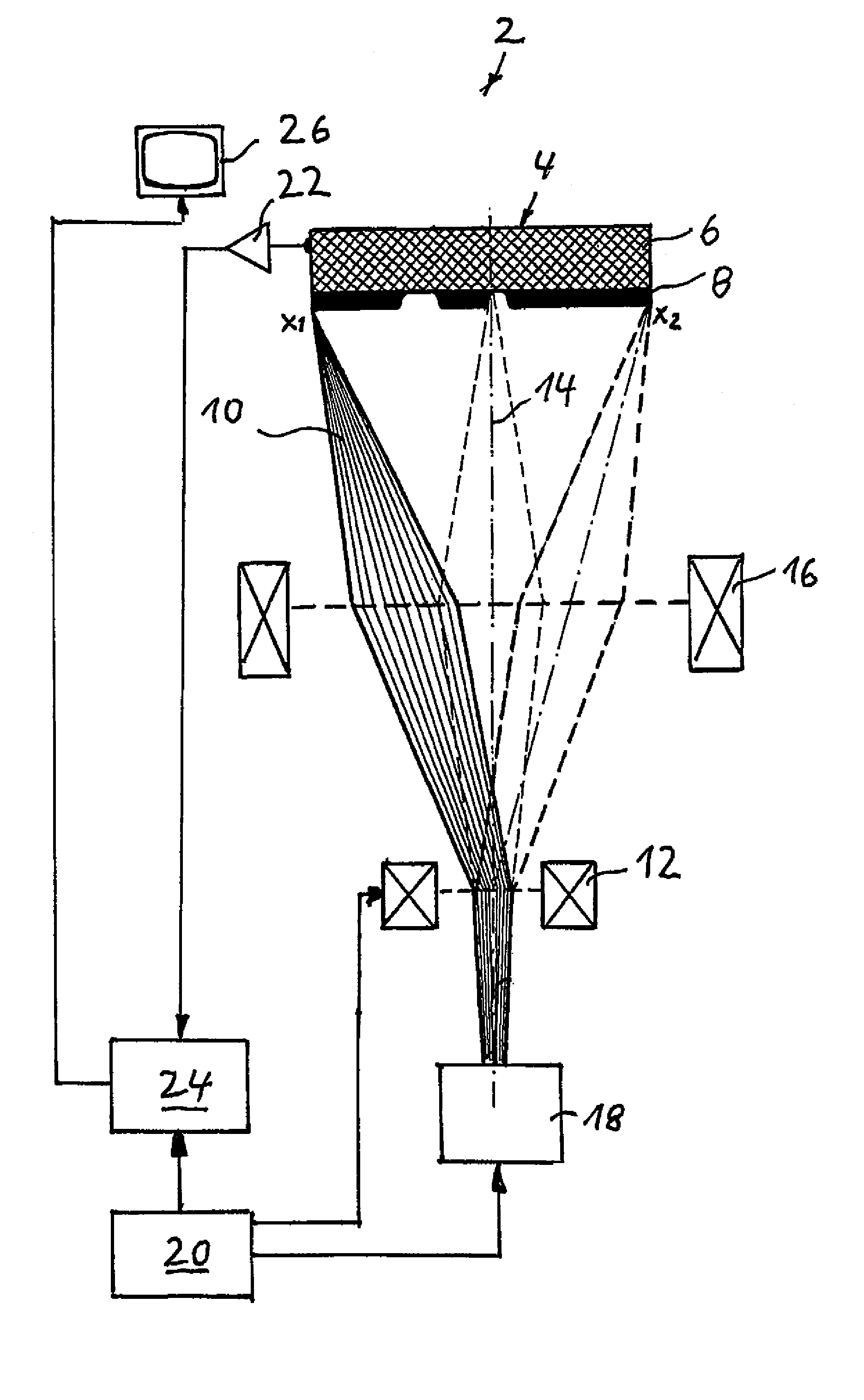
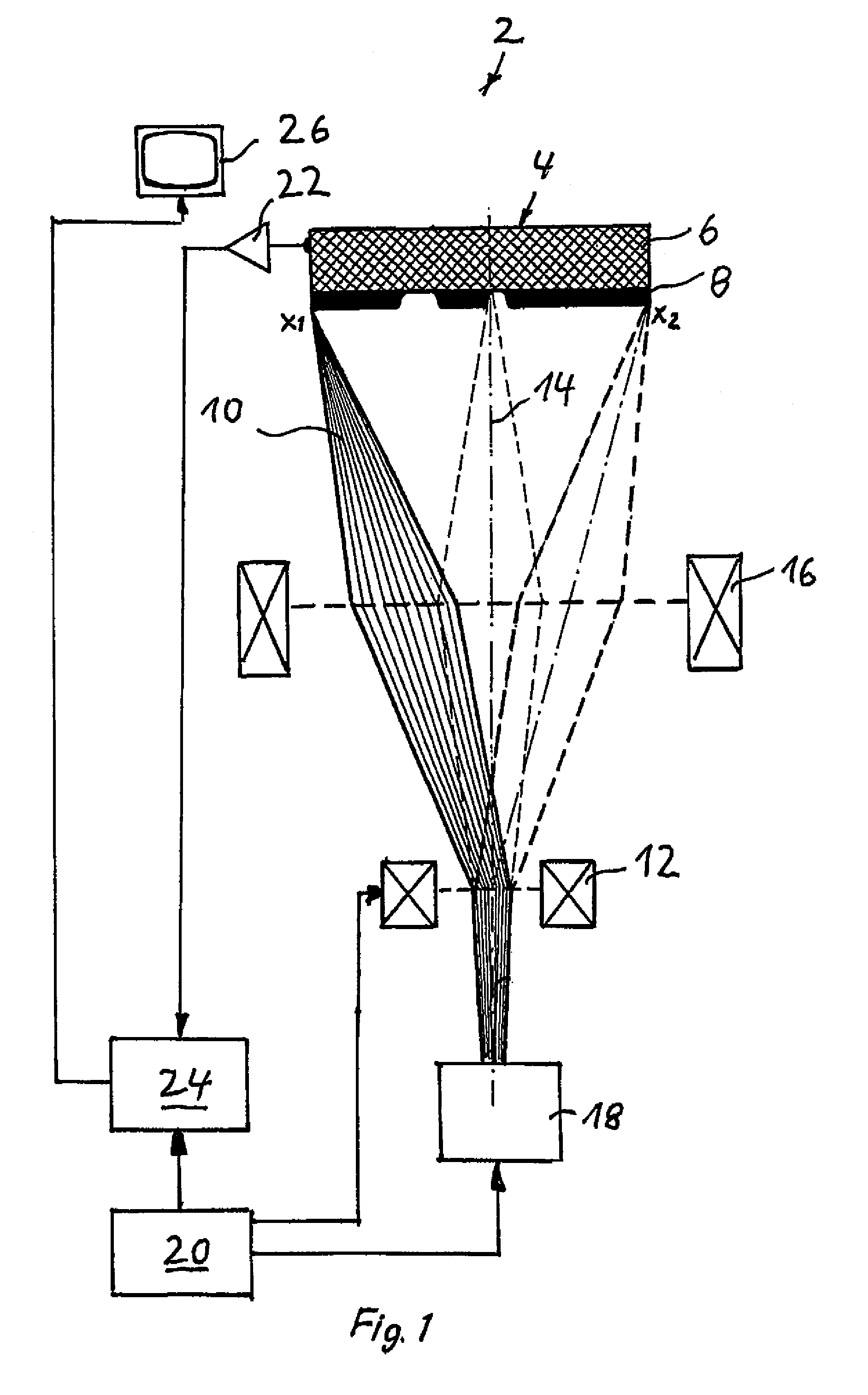
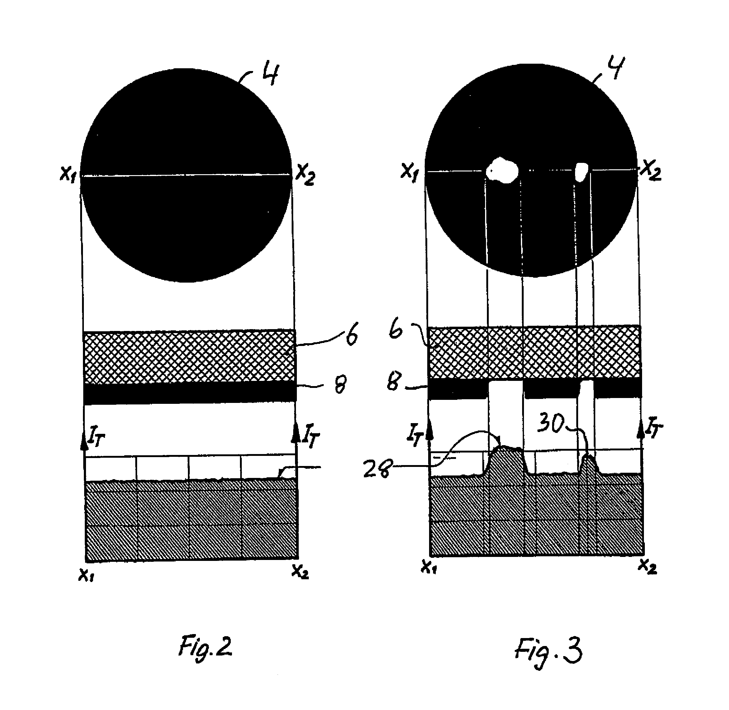
[0030]FIG. 1 shows an embodiment of an X-ray tube according to the invention in the form of a microfocus X-ray tube 2 which includes a target 4. The target 4 has a base body 6, consisting of a support material, in this embodiment beryllium, to which a target layer 8, consisting of a target material, in this embodiment tungsten, is applied.

[0031]The X-ray tube 2 also has means for directing an electron beam, indicated by the reference number 10 in FIG. 1...


PUM


Abstract

The invention relates to an X-ray tube, especially a microfocus X-ray tube (2), comprising means (18) for orienting an electron beam (10) towards a target (4). A control device (20) is used to control the means for orienting the electron beam (10) towards the target (4) in such a way that the electron beam (10) scans the target (4), in addition to a measuring device (22) for measuring the intensity of the target current which flows to different scanning sites when the target (4) is scanned by the electron beam (10), or a measuring variable dependent on the target current, and an evaluation device (24) for associating each measured value of the target flow with the corresponding scanning site. Said X-ray tube enables the easy and economical implementation of a method for checking the operability of the target (4).

Description

[0001]This is a U.S. National Phase Application under 35 U.S.C. §171 of PCT / EP2007 / 011463, filed on Dec. 28, 2007, which claims priority to German Application No. DE 10 2006 062 452.1, filed Dec. 28, 2006. The International Application was published in German on Jul. 10, 2008, as WO 2008 / 080624 under PCT article 21 (2).[0002]The invention relates to an X-ray tube and a method for examining the target of an X-ray tube.BACKGROUND[0003]Such X-ray tubes are generally known for example in the form of microfocus X ray-tubes and are used for example to examine printed circuit boards in the electronics industry. The known X-ray tubes include a target which is struck by high-energy-accelerated electrons or other electrically charged particles when the X-ray tube is operating, with the result that X-radiation is produced in generally known manner. The thus-produced X-radiation is used in imaging methods in order for example to represent components or component arrays on printed circuit boards...

Claims


Application Information

Patent Timeline
Patent Type & Authority Patents(United States)
IPC IPC(8): G01D18/00H01J35/14
CPCH01J35/14H01J35/24H05G1/265H05G1/34H05G1/52H01J2235/08H01J35/153
Inventor REINHOLD, ALFRED
Owner COMET AG
Why Eureka
Try Eureka