Arrangement and method for the recording and display of images of a scene and/or an object

a technology applied in the field of arrangement and method for recording and displaying images of scenes and/or objects, can solve the problems of large implementation effort, increased cost of using several cameras, and often not very precise sensors, etc., and achieve the effect of facilitating fixing

Inactive Publication Date: 2012-12-11
KONINKLIJKE PHILIPS NV
View PDF18 Cites 19 Cited by
  • Summary
  • Abstract
  • Description
  • Claims
  • Application Information

AI Technical Summary

Benefits of technology

[0011]In all, three cameras, i.e. at least one main and two satellite cameras or at least two main and one satellite camera, are provided. Main and satellite cameras generally, but not imperatively, differ by their quality. Mostly, the main camera is a high-quality camera, whereas the satellite cameras may be of lesser quality (e.g., industrial cameras) and thus mostly, but not imperatively, have a lower resolution, among other parameters. Essentially, the advantage of the invention is that, rather than the classical stereocamera system, here consisting essentially of two identical high-resolution cameras, a three-camera system is used, preferably consisting of a central high-quality camera and two additional cameras of lower resolution, arranged to the left and right, respectively, of the main camera. In other words, the main camera is preferably arranged between the satellite cameras. The distances between the cameras and their alignment (either in parallel or pointed at a common focus) are variable within customary limits. The use of further satellite cameras may be of advantage, as this enables a further reduction of misinterpretations especially during the subsequent processing of the image data. All cameras may be arranged in parallel or pointed at a common focus. It is also possible that not all of them are pointed at a common focus (convergence angle). The optical axes of the cameras may lie in one plane or in different planes, with the center points of the objectives preferably arranged in line or on a (preferably isosceles or equilateral) triangle. For special cases of application, the center points of the cameras' objectives may also be spaced at unequal distances relative to each other (with the objective center points forming a scalene triangle). It is further possible that all (at least three) cameras (i.e. all existing main and satellite cameras) differ by at least one parameter, e.g. by their resolution. The cameras should be synchronized with regard to zoom, f-stop, focus etc. as well as with regard to the individual frames (i.e. true-to-frame synchronization in recording). The cameras may be fixed at permanent locations or movable relative to each other; the setting of both the base distance between the cameras and the convergence angles may be automatic.
[0012]It may be of advantage to provide adapter systems that facilitate fixing, especially the satellite cameras to the main camera. In this way, ordinary cameras can be subsequently converted into a 3D camera. It is also feasible, though, to convert an existing stereocamera system into a 3D camera conforming to the invention by retrofitting an added main camera.
[0013]Furthermore, the beam path—preferably in front of the objectives of the various cameras—can be provided with additional optical elements, e.g. semitransparent mirrors. This makes it possible, e.g., to arrange each of two satellite cameras rotated 90 degrees relative to the main camera, so that the camera bodies of all three cameras are arranged in such a way that their objective center points are closer together horizontally than they would be if all three cameras were arranged immediately side by side, in which case the dimension of the camera bodies would necessitate a certain, greater spacing of the objective center points. In the constellation with the two satellite cameras rotated 90 degrees, a semitransparent mirror arranged at an angle of about 45 degrees relative to the principal rays emerging from the objectives of the satellite cameras would follow in reflection position, whereas the same mirror arranged at an angle of also 45 degrees relative to the principal ray emerging from the objective of the main camera follows in transmission position.
[0014]Preferably, the objective center points of the main camera and of at least two satellite cameras form an isosceles triangle.
[0015]For special embodiments it may also be useful to use black-and-white cameras as satellite cameras, and subsequently automatically assign a tonal value preferably to the images produced by them.
[0016]The problem is also solved by a method for the recording and display of images of a scene and / or an object, comprising the following steps:

Problems solved by technology

The downside is the great efforts needed to implement an exact alignment of the—e.g., eight—cameras relative to each other.
Another drawback is the increased cost involved in using several cameras, which, in addition, entail further problems such as different white levels, tonal values / geometric data, which have to be balanced accordingly.
Third, the use of a depth camera. This means the use of a color camera jointly with a depth sensor, which registers the—as a rule, cyclopean—depth information of the scene to be recorded. Apart from the fact that a depth sensor is relatively expensive, it is a disadvantage that these sensors often do not work very exactly, and / or that no acceptable compromise between accuracy and speed is achieved. General extrapolation is required, artefacts cannot be excluded especially in the outer views, and generally, occluding artefacts cannot be covered up.

Method used


Image

  • Arrangement and method for the recording and display of images of a scene and/or an object
  • Arrangement and method for the recording and display of images of a scene and/or an object
  • Arrangement and method for the recording and display of images of a scene and/or an object

Examples


Embodiment Construction

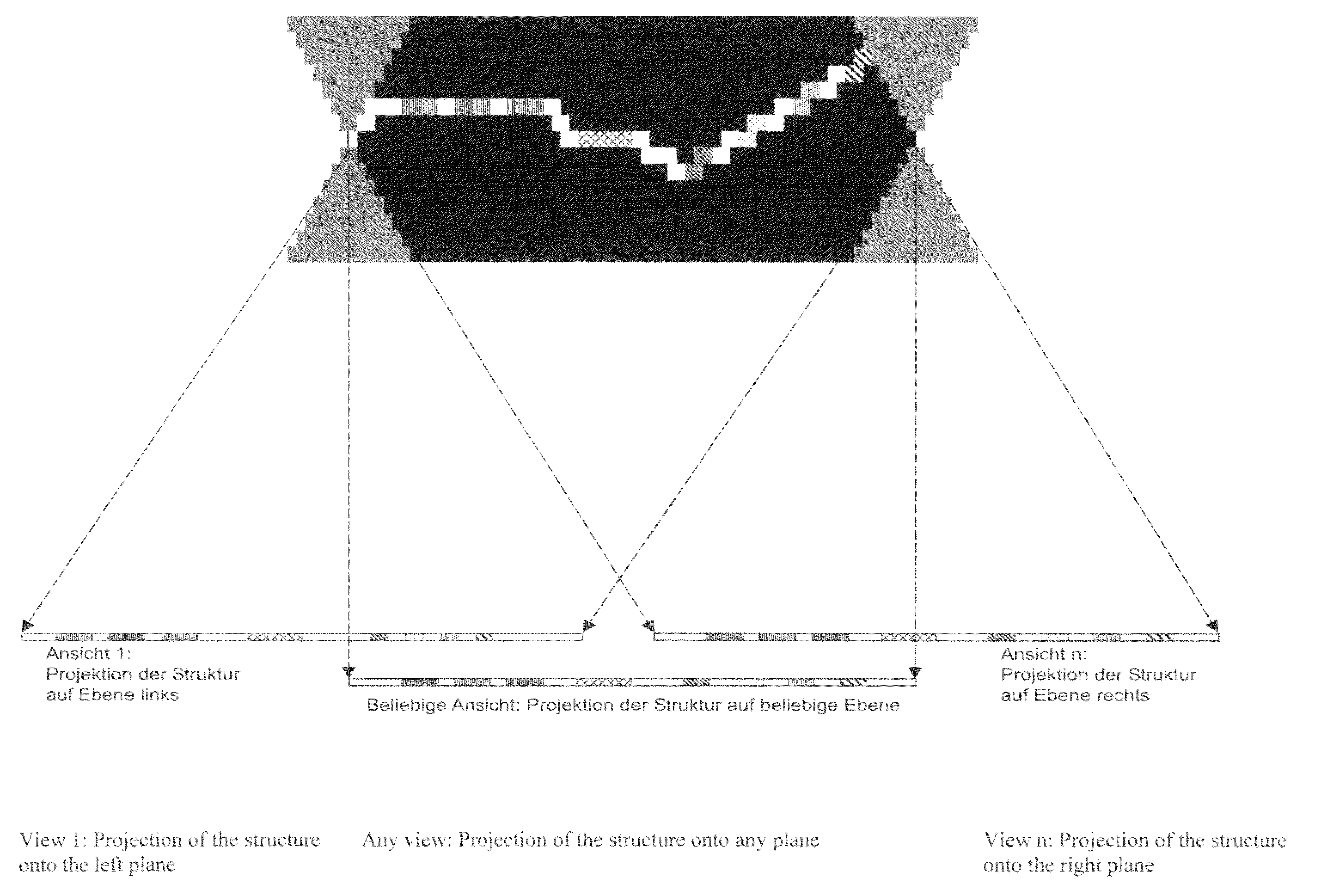
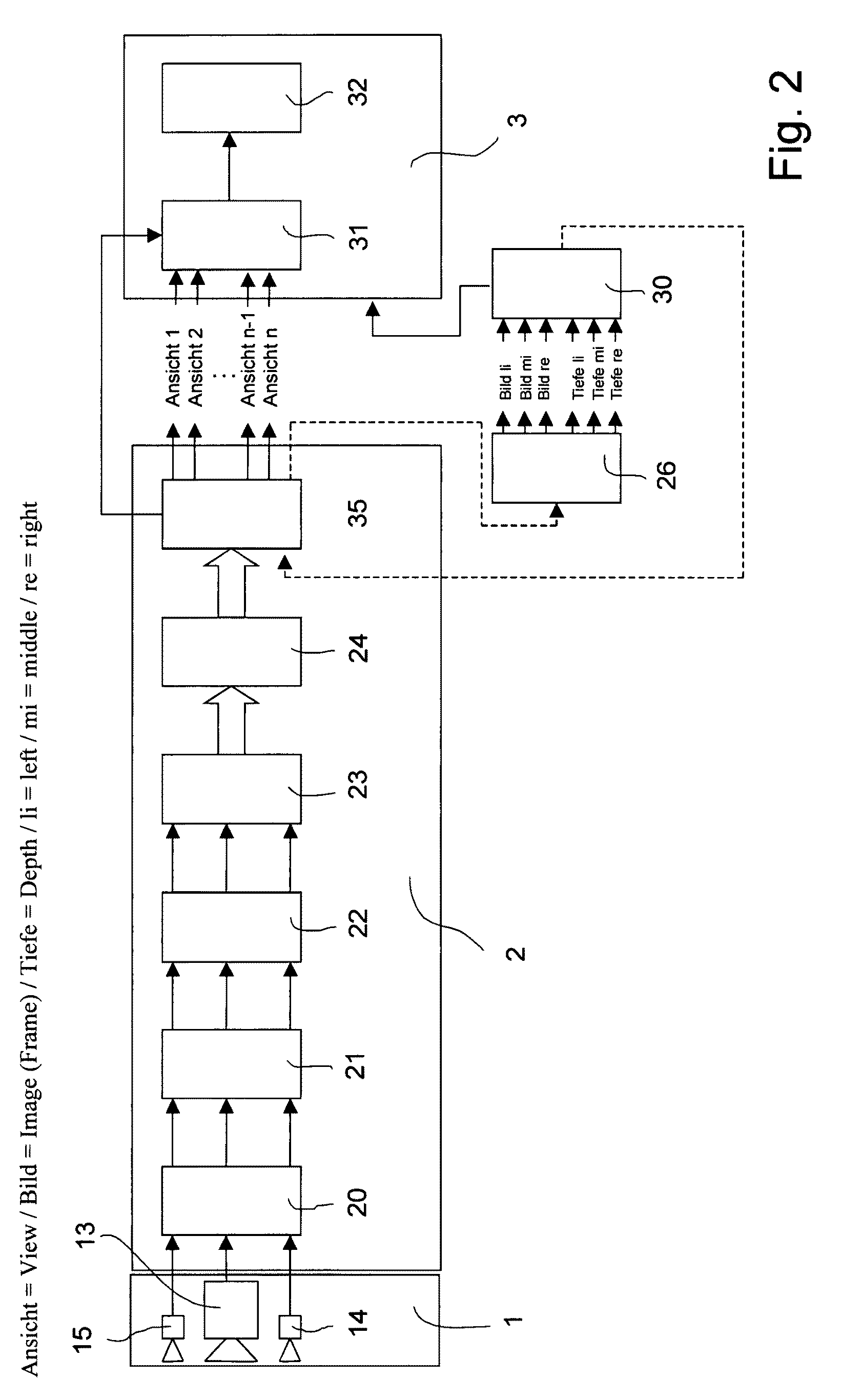
[0048]An arrangement according to the invention essentially consists of a stereocamera system 1, an image conversion device 2 and a 3D image display device 3. As shown in FIG. 1, the stereocamera system 1 contains a right camera 11 and a left camera 12, the image conversion device 2 contains a rectification unit 21, a color adjustment nit 22, a unit for establishing the stack structure 23, a unit for the optimization of the stack structure 24, and a unit 25 for the projection of the stack structure onto the desired view, and the 3D image display device 3 contains an image combination unit 31 and a 3D display 32, with the 3D display 32 displaying at least three views of a scene / of an object for spatial presentation. The 3D display 32 can also work on the basis of, say, 4, 5, 6, 7, 8, 9 or even more views. As an example, a 3D display 32 of model “Spatial View 19 inch” is eligible. FIG. 2 shows another arrangement according to the invention. Here, the 3D camera system 1 contains a main...


PUM


Abstract

The invention relates to an arrangement and a method for the recording and display of images of a scene and / or an object. They are suitable especially for the spatially perceived display of the recorded images. The problem of finding a new way of recording, with the least possible effort, images of real scenes or objects and subsequently displaying them three-dimensionally in two or more views by autostereoscopy is solved, according to the invention, in such a way that at least one main camera of a first camera type and at least one satellite camera of a second camera type are provided for the recording of images, with an image conversion device and a 3D image display device being arranged downstream of the cameras. The two camera types differ in at least one parameter; and a total of at least three cameras are provided. The invention also comprises a method for the transmission of 3D information.

Description

CROSS-REFERENCE TO RELATED APPLICATIONS[0001]This application claims priority of International Application No. PCT / DE2007 / 000786, filed Apr. 27, 2007 and German Application No. 10 2006 055 641.0, filed Nov. 22, 2006, the complete disclosures of which are hereby incorporated by reference.BACKGROUND OF THE INVENTION[0002]a) Field of the Invention[0003]The invention relates to an arrangement and a method for the recording and display of images (frames) of a scene and / or an object, suitable especially for the display of the recorded images for spatial perception. The invention further relates to a method for the transmission of images for spatial perception.[0004]b) Description of the Related Art[0005]At present there are essentially three basically different methods, and the appertaining arrangements, for recording 3D image information.[0006]First, the classical stereocamera, consisting of two like cameras for a left and a right image. For a highly resolved display, high-resolving came...

Claims


Application Information

Patent Timeline
Patent Type & Authority Patents(United States)
IPC IPC(8): H04N7/00H04N13/00H04N13/02H04N13/133H04N13/395
CPCH04N13/0025H04N13/025H04N13/0495H04N13/0011H04N13/0059H04N13/0239H04N13/0242H04N19/597H04N13/0285H04N13/0402H04N13/0429H04N13/044H04N2013/0081H04N13/0282H04N13/302H04N13/395H04N13/243H04N13/344H04N13/194H04N13/282H04N13/111H04N13/332H04N13/286H04N13/239H04N13/25H04N13/133
Inventor SCHMIDT, ALEXANDERMEICHSNER, JENSBILLERT, RONNY
Owner KONINKLIJKE PHILIPS NV
Why Eureka
Try Eureka