
Campfire smokestack and method

a technology of a smokestack and a nozzle, which is applied in the direction of domestic stoves or ranges, lighting and heating apparatus, combustion processes, etc., can solve the problems of limiting the size of the fire that it can accommodate, not being suited to use with open, ground-based campfires of decent size, and not being able to meet the needs of campers, so as to improve the efficiency, start and maintain, and improve the effect of efficiency

Inactive Publication Date: 2012-12-11
JUDGE MARC A +2
View PDF14 Cites 8 Cited by
  • Summary
  • Abstract
  • Description
  • Claims
  • Application Information

AI Technical Summary

Benefits of technology

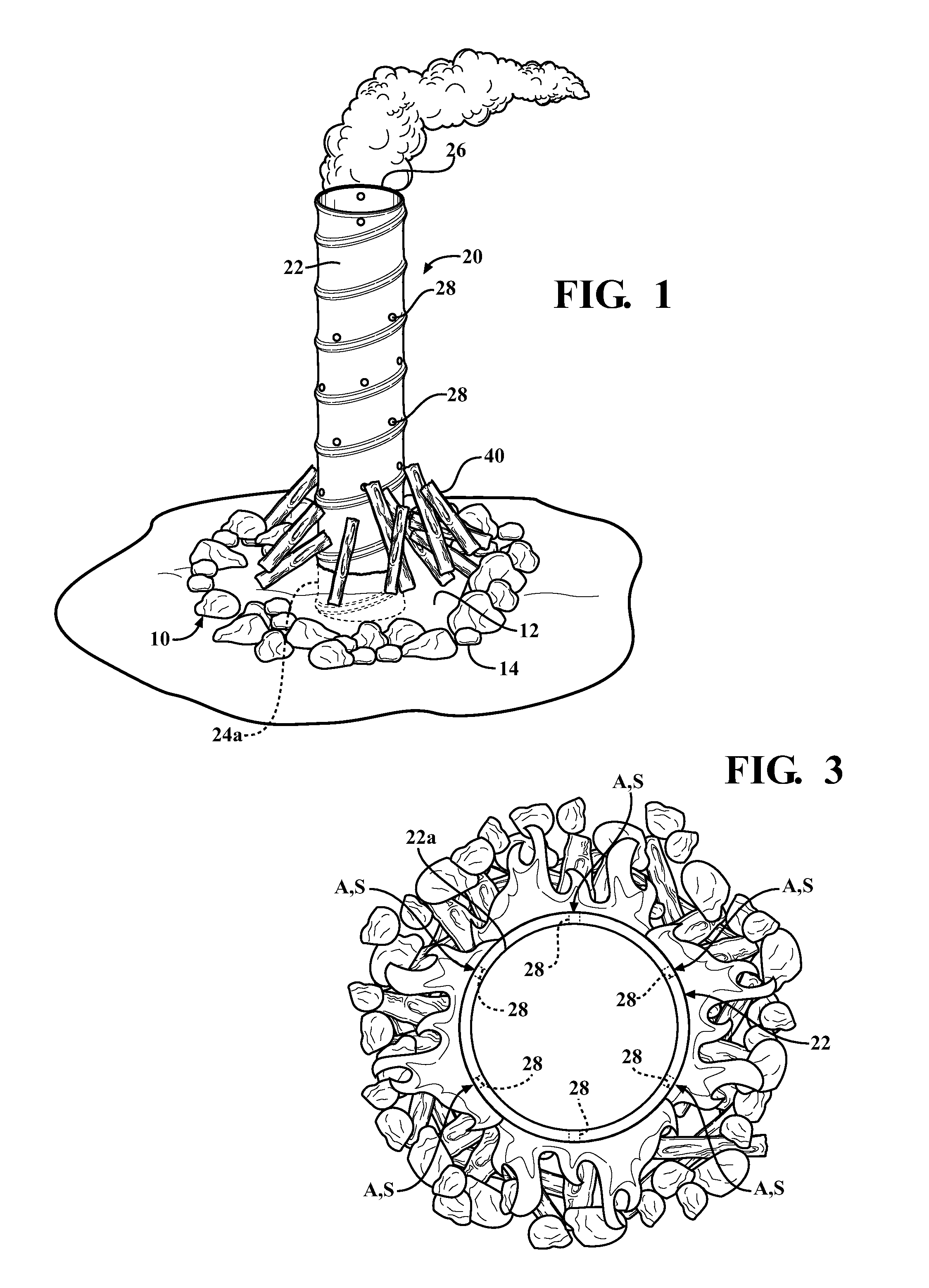
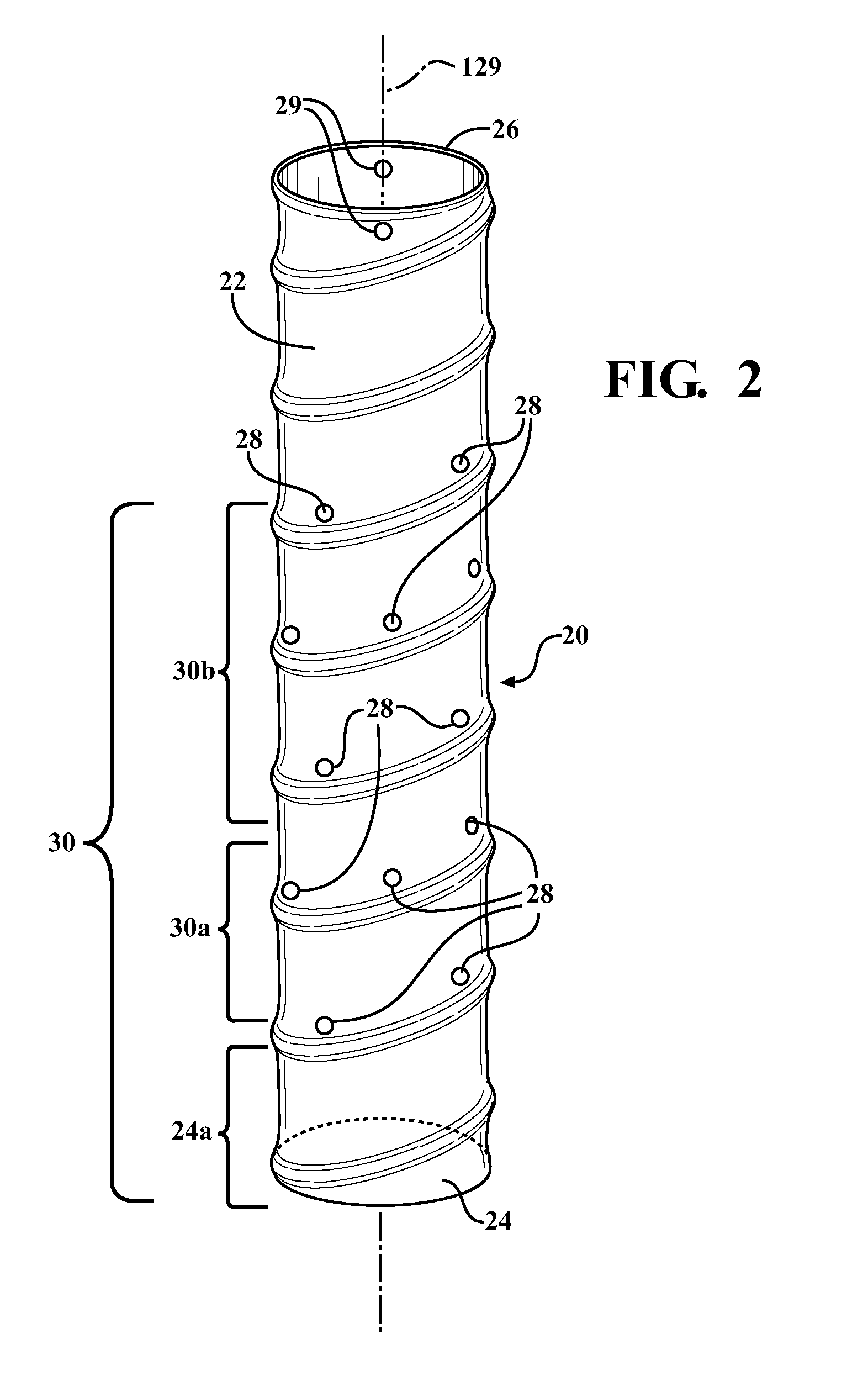
"The invention is a portable and efficient smokestack for ground-based camfires that improves the warmth and fun of the fire. It draws the smoke generated by the fire up and away from people, enhancing the fire's visual enjoyment. The smokestack is easy to use, portable, and does not require any special base or digging. It can be left in the fire from start to finish and can be relocated to other camfires. The smokestack is an upright tube with draft openings that allow air and smoke to flow through it. It can be anchored to the ground or fire-pit and can contain combustibles for a visual effect called the afterburner effect. The draft openings in the lower end of the tube define the draft level of the fire and can be located high enough to illuminate the upper part of the tube. The upper end of the tube can also have holes or hooks for lifting it out of the fire pit."

Problems solved by technology

Campers are also familiar with difficulty in lighting and maintaining a campfire, for example when using substandard wood or in poor weather conditions.
With the exceptions of the Armstrong et al and Whitted devices, none of the above appears to be suited for use with open, ground-based campfires of decent size, around which groups of campers like to congregate in the evening.
Armstrong et al's device, although designed for campfires, would obscure a significant portion of the fire underneath and would limit the size of the fire that it accommodates.
Whitted's device appears to be intended for efficient cooking with a ground-based wood fire, but not for visually enjoying the flames of an open campfire, as it encloses the fire with a metal wall.

Method used


Image

  • Campfire smokestack and method
  • Campfire smokestack and method
  • Campfire smokestack and method

Examples


Embodiment Construction

[0022]Referring first to FIGS. 1 through 3, a campfire smokestack 20 is shown in exemplary form in order to teach how to make and use the claimed invention. Smokestack 20 is formed from a tube 22 of metal, in the illustrated example a four- to five-foot length of light-gauge steel stovepipe, for example in the range of three to six inches in diameter, and preferably strong enough to hold its shape when subjected to the heat of a campfire over one or more seasons of use, although one-time use or short-term use versions are possible using thinner or lighter-gauge materials. The length and diameter of the tube can vary, being shorter or longer and / or wider or narrower than the illustrated example, with corresponding affect on the draft. Tube 22 can be a single long tube or multiple tube sections assembled or telescoped together, without limitation as to how the final elongated tube shape is achieved. Tube 22 preferably has a circular cross-section, but can have other cross-sectional sh...


PUM


Abstract

A campfire smokestack comprising an elongated metal tube whose lower end is anchored in a fire pit, for example by burying it in the ground, prior to making a fire, or by placing it into an existing fire. The tube has an open upper end, and its sidewall is perforated over some portion of its length with draft openings, at least some of which are at campfire height such that the fire is built against or adjacent these lower draft openings to permit radial drafting of air directly through the fire into the tube. The fire is accordingly built and burned around or against the lower end of the tube, rather than within or underneath the tube. The smokestack may be used with both natural and manmade fire pits.

Description

RELATED APPLICATIONS / PRIORITY BENEFIT CLAIM[0001]The present application claims the benefit of the priority of U.S. provisional patent application No. 61 / 181,793 filed May 28, 2009 by the same inventors (Judge, Francis, and Grant), the entirety of which provisional patent application is incorporated by reference.FIELD OF THE INVENTIVE SUBJECT MATTER[0002]The subject matter of the present application is in the field of tubular draft-inducing devices used with outdoor fires.BACKGROUND AND DESCRIPTION OF RELATED ART[0003]Campers are familiar with the “smoke in your eyes” phenomenon in which, no matter where they move around the fire, smoke seems to follow them. Campers are also familiar with difficulty in lighting and maintaining a campfire, for example when using substandard wood or in poor weather conditions. Despite these drawbacks, the campfire and its flames are always the center of attention, camaraderie, entertainment and warmth during campouts and other outdoor activities.[0004...

Claims


Application Information

Patent Timeline
Patent Type & Authority Patents(United States)
IPC IPC(8): F24B3/00
CPCF24B3/00F23J11/00
Inventor JUDGE, MARC A.FRANCIS, JOSEPH JGRANT, JAMES A.
Owner JUDGE MARC A
Learn More