
Electrolyser module

a technology of electrolyser module and electrolyser, which is applied in the direction of instruments, cells, photographic processes, etc., can solve the problems of affecting the availability of electrolyser modules, capital and operating costs, maintenance requirements, and maximum associated power loss, and achieves good gas-liquid separation efficiency and high liquid circulation rate

Active Publication Date: 2012-11-13
NEXT HYDROGEN CORP
View PDF7 Cites 26 Cited by
  • Summary
  • Abstract
  • Description
  • Claims
  • Application Information

AI Technical Summary

Problems solved by technology

For example, the use of a pump adds complexity, capital and operating cost, maintenance requirements, and may adversely affect the availability of the electrolyser module.
The pump generally is operated at all times during module operation at a liquid flow rate corresponding to that required for the maximum nominal gas production rate, resulting in maximum associated power losses.
Although a dual mechanical pump electrolyser module configuration also is disclosed, typically in practical (commercial) electrolyser modules, a single mechanical pump circuit is used to circulate liquid collected from both degassing chambers back to both the cathode half cell chambers and anode half cell chambers; this maintains equal pressures on either side of the membrane in each cell, but typically adversely affects gas purities by introducing the other gas (entrained in the returning liquid) into both the anode and cathode half cell chambers.
Advantages of this design approach are the potential to maintain high gas purities and inherently self-regulating fluid flows; however, the number of cells per cell stack is limited by the pressure drop across the horizontal manifolds in the cell stack and the external piping or tubing, and the available vertical space to provide pressure head.
Consequently, this particular approach generally has been limited to relatively small production capacities, with an associated requirement to use multiple cell stacks or multiple complete electrolyser modules to reach higher production capacities.
This approach, while somewhat more scaleable in terms of the number of cells in a single cell stack, requires a significant amount of piping and assembly, with many mechanical connection points, each representing a potential leak point.
Furthermore, scalability remains limited by pressure drops across the common degassed liquid return path, i.e., the external piping or tubing and manifold beneath the half cell chambers in the bottom portion of the cell stack.
In all of the above approaches, the physical size of the electrolyser module, i.e., its lack of compactness for any given hydrogen gas production capacity, is problematic.
However, none of these designs addresses the other drawbacks described above.
While the anode and cathode half cells are maintained completely separate in these designs, the number of cells per stack is limited by the pressure drop across the horizontal manifolds, and the limited head available in the relatively compact module design.

Method used

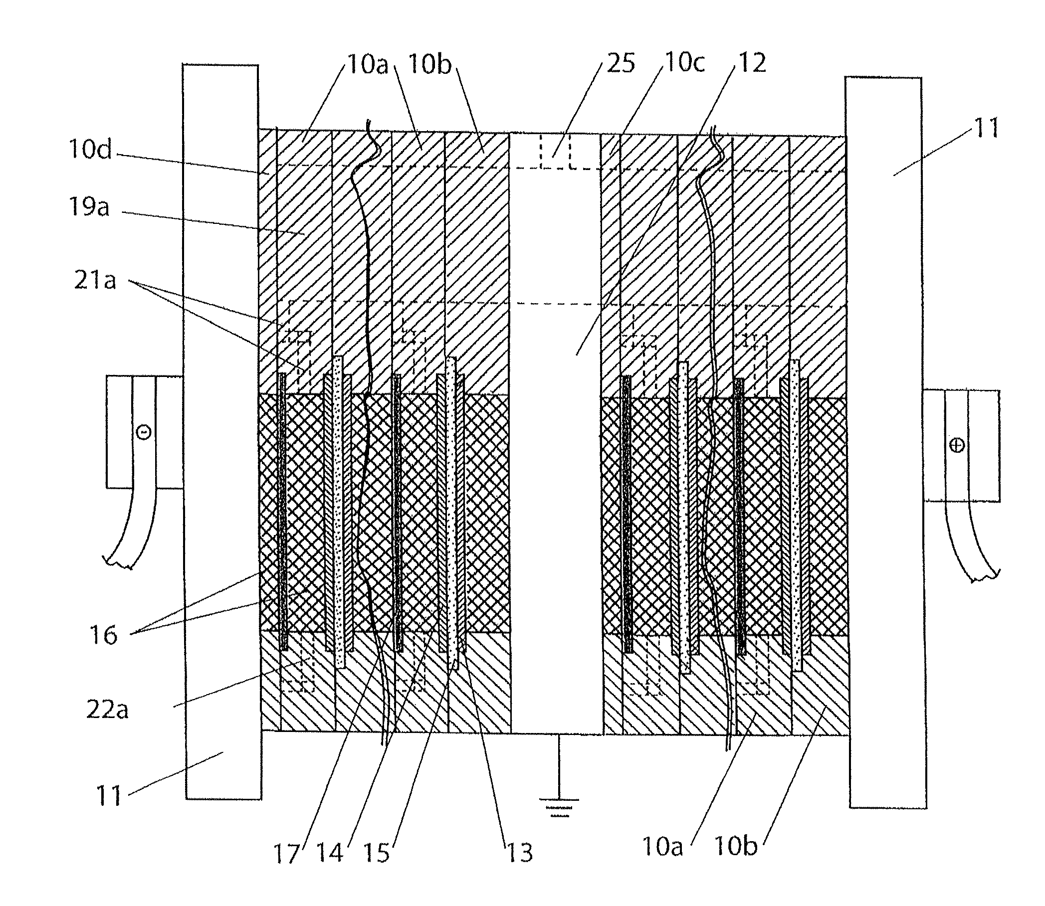
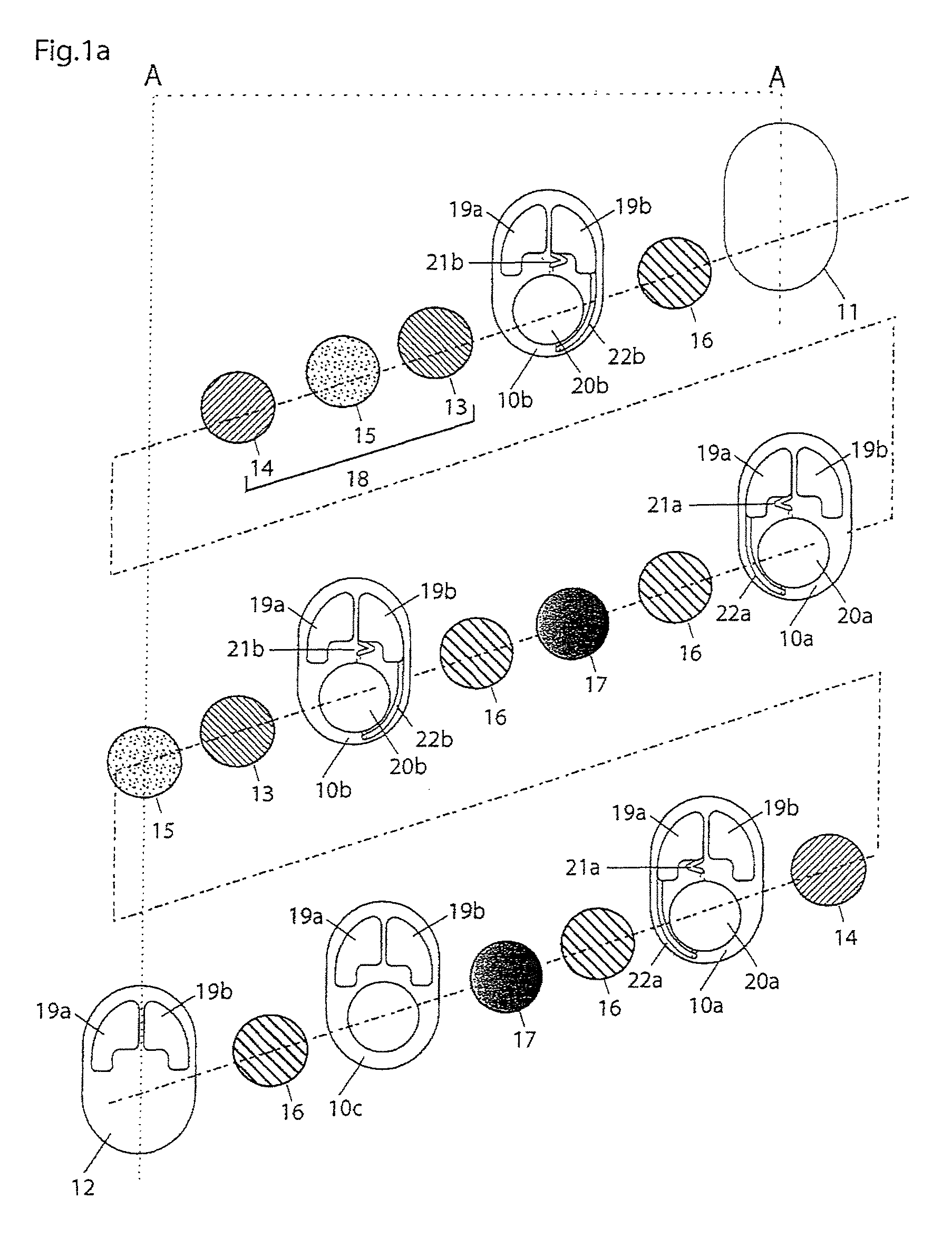
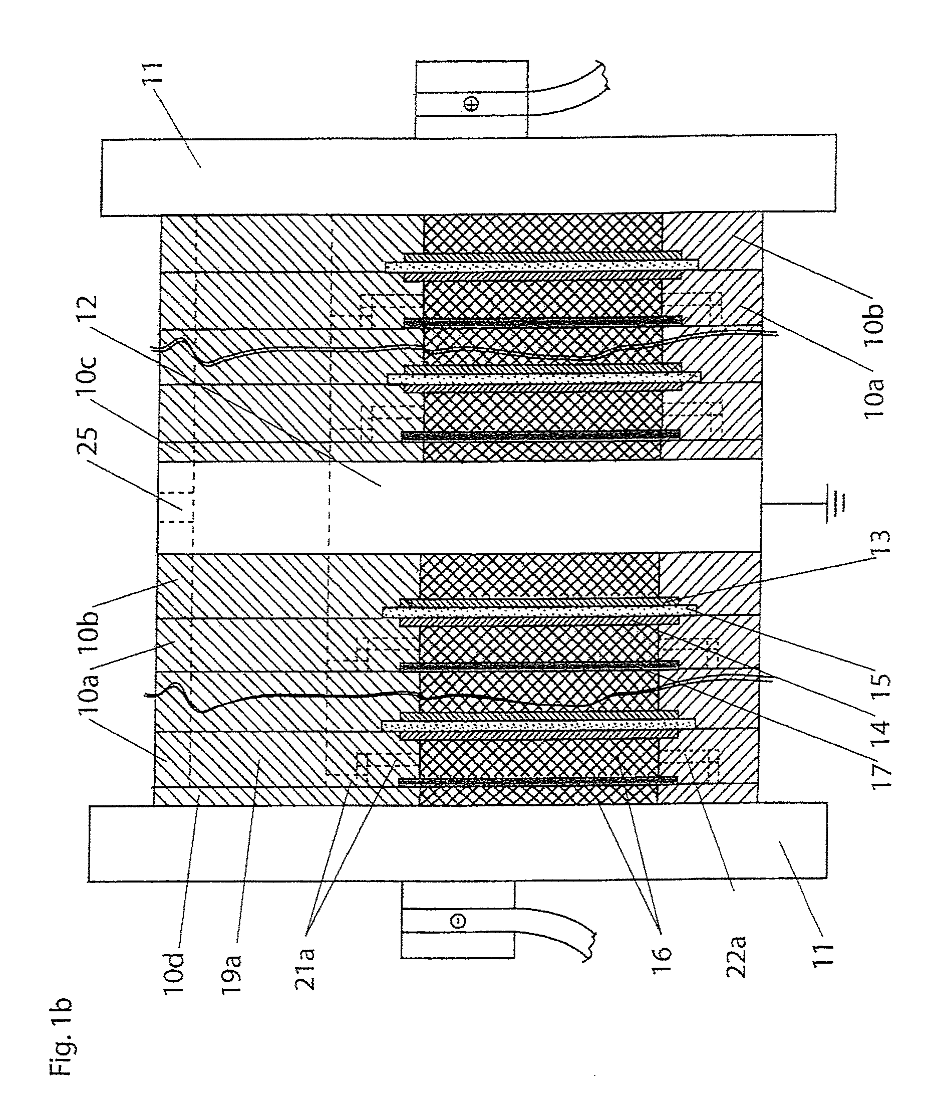

Image

  • Electrolyser module
  • Electrolyser module
  • Electrolyser module

Examples


example 1

[0090]The fluid flows in a six-cell electrolyser module according to the present invention were modeled by computational fluid dynamics (CFD). For simplicity, the fluid flows on the hydrogen (cathodes) side only are described herein. The general structural plate configuration was as shown in FIG. 3, in which the gas-liquid passage 21 extends from the top part of half cell chamber opening 20 and partway under corresponding degassing chamber opening 19a, then doubles back over itself before joining the bottom part of degassing chamber opening 19a at the near side. The cell active area was 6,000 cm2. The hydrogen gas-liquid separation chamber was comprised of a main section 30 cm×50 cm×13.2 cm. The cross sectional area of the gas-liquid passages and the degassed liquid passages was 3 cm2. The maximum current density was 1,000 mA / cm2. This corresponds to a maximum hydrogen generation rate per half cell of 2.5 Nm3 / h, so the ratio of maximum hydrogen generation rate per half cell to the c...

example 2

[0091]Next, the number of cells in the electrolyser module of Example 1 was increased to 50 cells. The fluid flows in the 50-cell electrolyser module were modeled by CFD. For simplicity, the fluid flows on the hydrogen (cathodes) side only are described herein. The results for each half cell were similar to those obtained for half cells in the six-cell electrolyser module, demonstrating the inherent scalability of the design. For example, fluid flow rates in any of the degassed liquid passages in the 50-cell electrolyser module were within 6% of fluid flow rates in any of the degassed liquid passages in the six-cell electrolyser module. Furthermore: (i) fluid flow rates in degassed liquid passages were higher in the 50-cell electrolyser module than in the six-cell electrolyser module, and (ii) the fluid flow rates in the degassed liquid passages for each of the 50 cathode half cells were within 1% of each other. Similarly, void fractions at the tops of the 50 cathode half cell chamb...

example 3

[0092]Next, the number of cells in the electrolyser module of Example 2 was increased to 200 cells. The fluid flows in the 200-cell electrolyser module were modeled by CFD. For simplicity, the fluid flows on the hydrogen (cathodes) side only are described herein. The results for each half cell were similar to those obtained for half cells in six-cell and 50-cell electrolyser modules, demonstrating the inherent scalability of the design. For example, the range of fluid flow rates in the degassed liquid passages in the 200-cell electrolyser module was identical to the range of fluid flow rates in the degassed liquid passages in the 50-cell electrolyser module. Similarly, void fractions at the tops of the 200 cathode half cell chambers were almost equal, and also were almost equal to the void fractions at the tops of the cathode half cell chambers in the 50-cell electrolyser module.

[0093]The present electrolyser modules can be used in the production of various gases, for example chlori...


PUM

PropertyMeasurementUnit
current efficienciesaaaaaaaaaa
aspect ratioaaaaaaaaaa
diameteraaaaaaaaaa

Abstract

An electrolyser module comprising a plurality of structural plates each having a sidewall extending between opposite end faces with a half cell chamber opening and at least two degassing chamber openings extending through the structural plate between the opposite end faces.

Description

FIELD OF THE INVENTION[0001]The present invention relates to the design of electrolysers for the production of gases such as hydrogen and oxygen, or hydrogen and nitrogen, or hydrogen and chlorine, and more particularly, to a water electrolyser module and components therefor.BACKGROUND OF THE INVENTION[0002]Electrolysers use electricity to transform reactant chemicals to desired product chemicals through electrochemical reactions, i.e., reactions that occur at electrodes that are in contact with an electrolyte. Hydrogen is a product chemical of increasing demand for use in chemical processes, and also potentially for use in hydrogen vehicles powered by hydrogen fuel cell engines or hydrogen internal combustion engines (or hybrid hydrogen vehicles, also partially powered by batteries). Electrolysers that can produce hydrogen include: water electrolysers, which produce hydrogen and oxygen from water and electricity; ammonia electrolysers, which produce hydrogen and nitrogen from ammon...

Claims


Application Information

Patent Timeline
Patent Type & Authority Patents(United States)
IPC IPC(8): C25B9/08C25B9/19
CPCC25B1/00C25B9/18C25B1/02Y02E60/366C25B9/70Y02E60/36
Inventor HINATSU, JIMSTEMP, MICHAEL
Owner NEXT HYDROGEN CORP
Learn More