
Testing device for an electronic device having two pivot points

a technology of electronic devices and pivot points, which is applied in the direction of testing manufactured objects, electrical apparatus casings/cabinets/drawers, instruments, etc., can solve the problems that the testing device cannot test the opening and closing actions in a single axial direction, and the testing procedure is different from the actual use of the foldable electronic devi

Inactive Publication Date: 2012-11-06
INVENTEC CORP
View PDF11 Cites 24 Cited by
  • Summary
  • Abstract
  • Description
  • Claims
  • Application Information

AI Technical Summary

Benefits of technology

[0019]As described above, the testing device provided by the present invention can test a foldable electronic device also in an axial direction between the second body and the first body besides the conventional signal axial direction.

Problems solved by technology

However, the conventional testing device can only test the opening and closing actions in a single axial direction but not the flipping action of the display screen.
Thus, the testing procedure is different from the actual use of the foldable electronic device.

Method used


Image

  • Testing device for an electronic device having two pivot points
  • Testing device for an electronic device having two pivot points
  • Testing device for an electronic device having two pivot points

Examples


Embodiment Construction

[0027]Reference will now be made in detail to the present preferred embodiments of the invention, examples of which are illustrated in the accompanying drawings. Wherever possible, the same reference numbers are used in the drawings and the description to refer to the same or like parts.

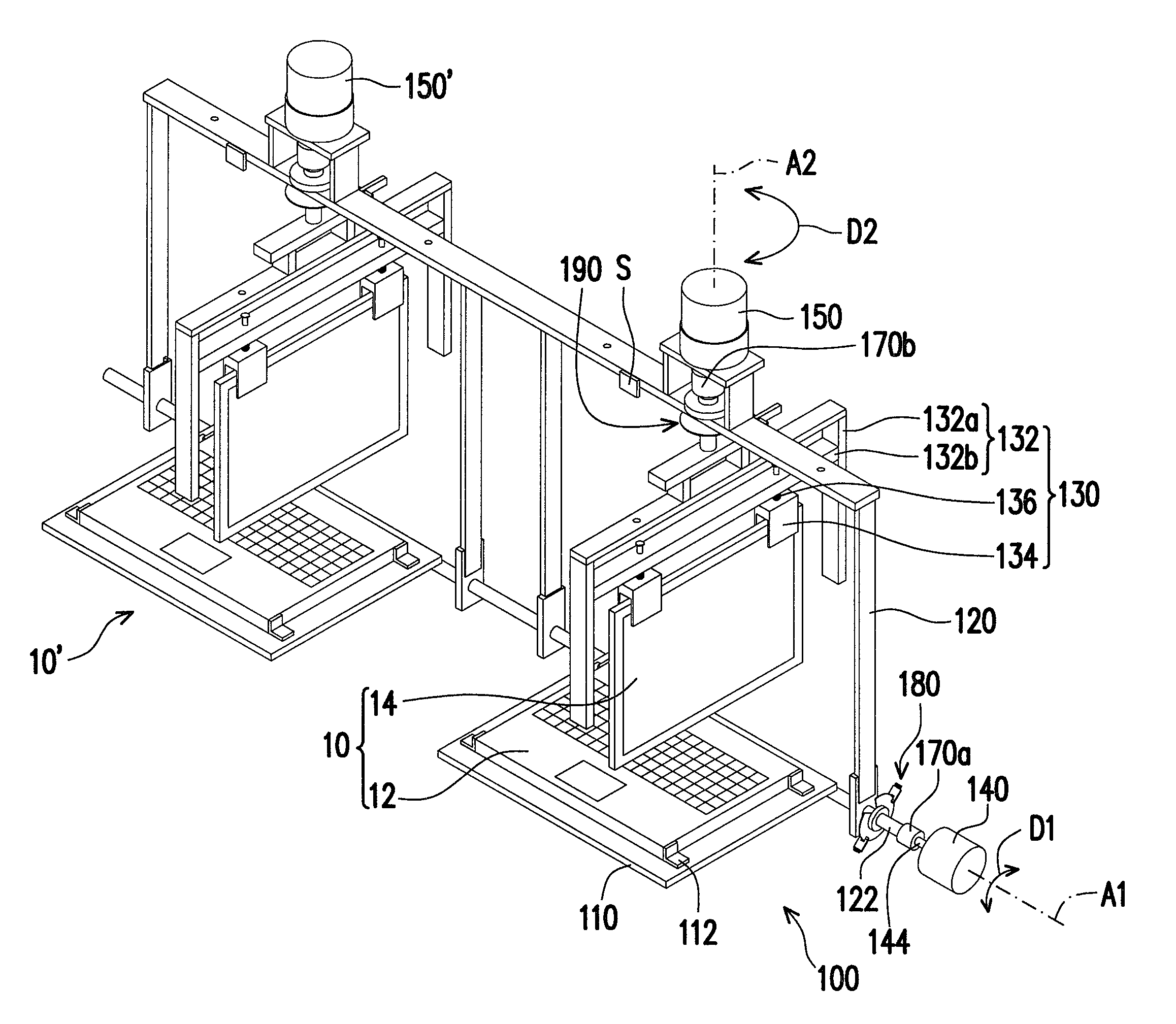
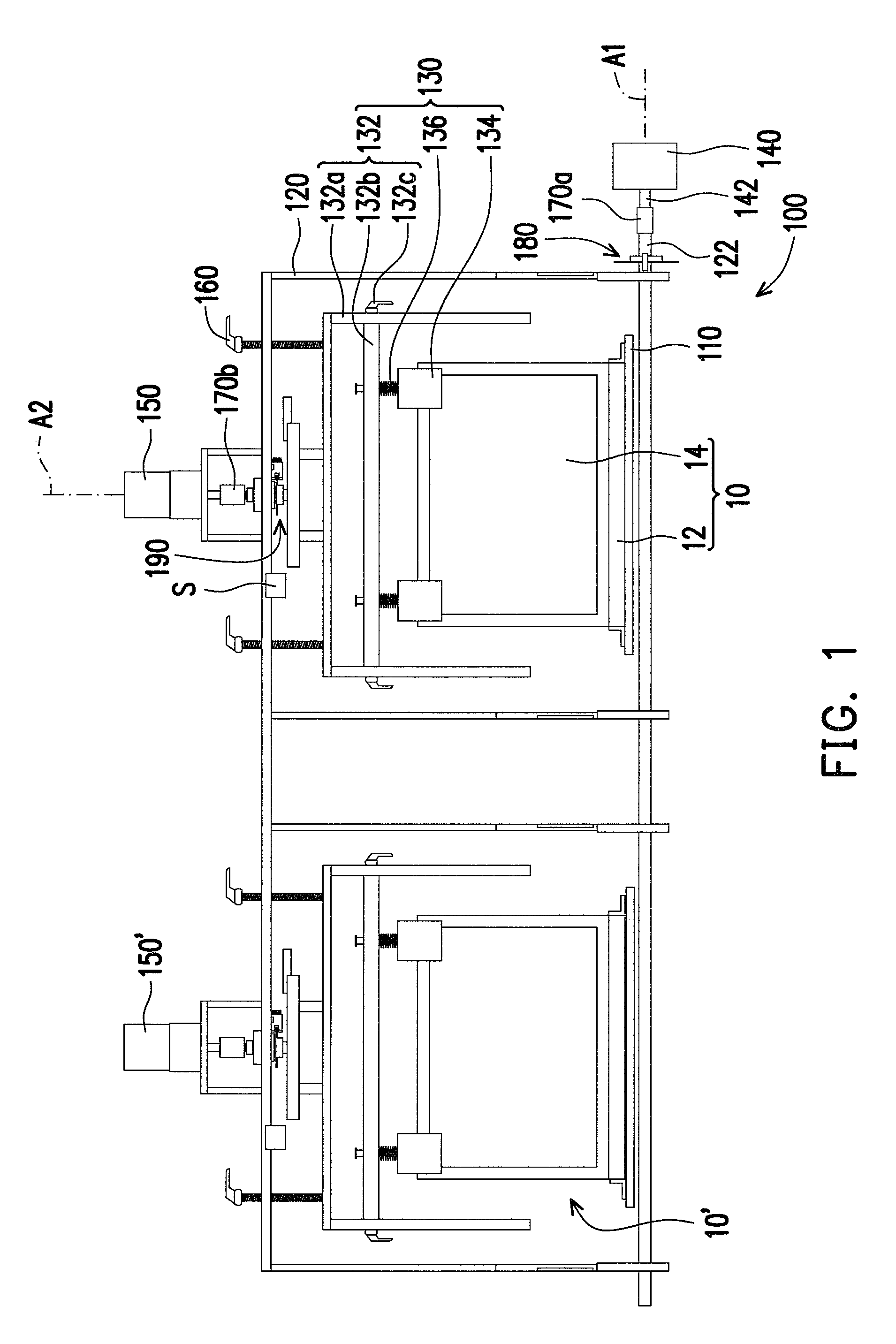
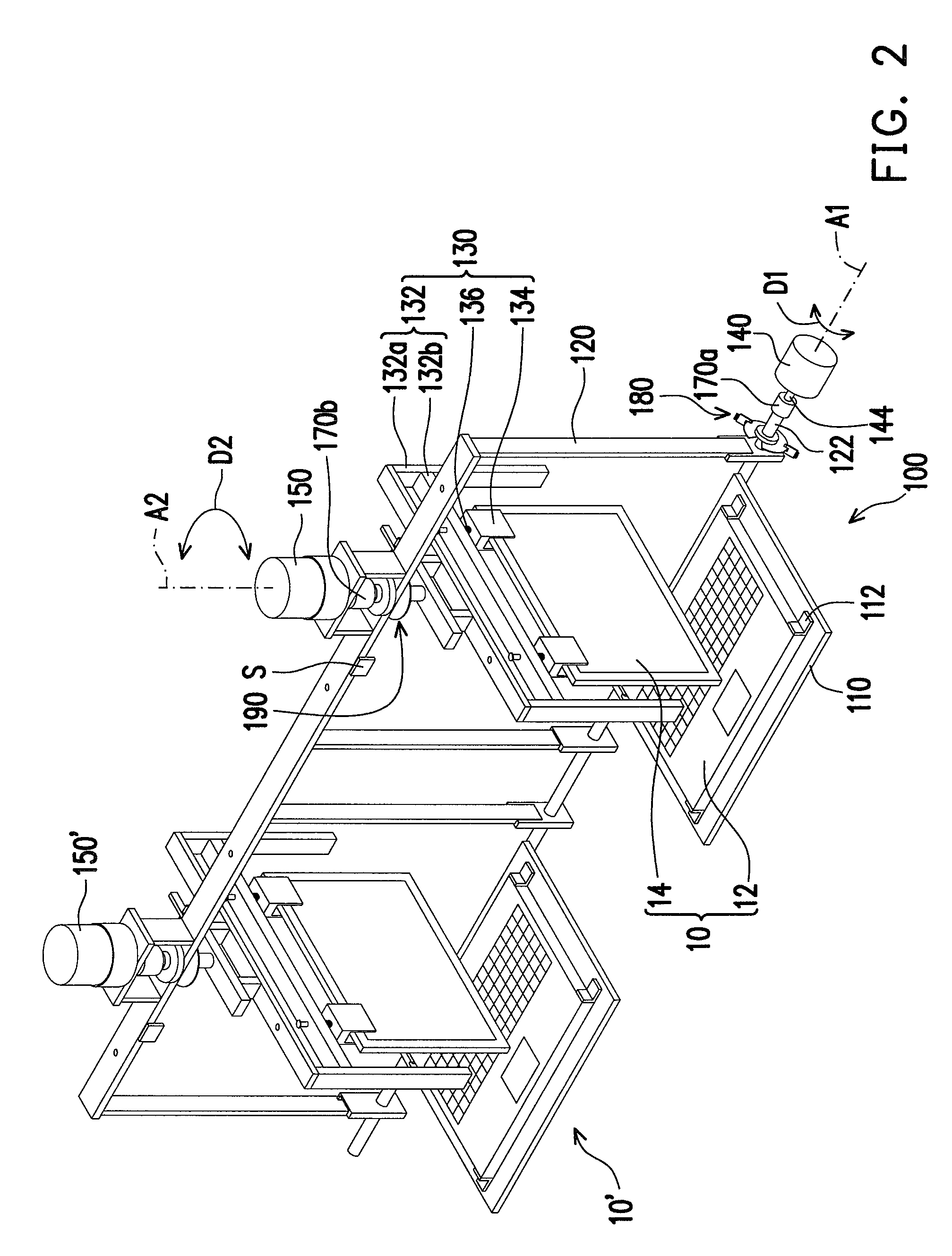
[0028]FIG. 1 is a front view illustrating how a testing device tests a foldable electronic device according to an embodiment of the present invention. FIG. 2 is a perspective view illustrating how the testing device flips a second body of the foldable electronic device in FIG. 1. Referring to FIG. 1 and FIG. 2, the testing device 100 is suitable for performing opening, closing, and rotation tests on a foldable electronic device 10. The foldable electronic device 10 may be a notebook PC, and which includes a first body 12, a second body 14, and a rotating shaft (not shown). The first body 12 may be the main body of the notebook PC, and the second body 14 may be the display screen of the notebook PC. T...


PUM

PropertyMeasurementUnit
angleaaaaaaaaaa
pivot angleaaaaaaaaaa

Abstract

A testing device suitable for testing an electronic device is provided. The electronic device has a first body and a second body, wherein the first body is suitable for rotating relative to the second body. The testing device includes a carrying platform, a fixed frame, a clamping element, a first driving element, and a second driving element. The carrying platform carries the first body. The fixed frame is pivoted to the carrying platform. The clamping element is pivoted to the fixed frame for clamping the second body. The first driving element is disposed between the carrying platform and the fixed frame for driving the fixed frame to pivot relative to the carrying platform. The second driving element is disposed between the clamping element and the fixed frame for driving the clamping element to pivot relative to the fixed frame.

Description

CROSS-REFERENCE TO RELATED APPLICATION[0001]This application claims the priority benefit of Taiwan application serial no. 99110756, filed on Apr. 7, 2010. The entirety of the above-mentioned patent application is hereby incorporated by reference herein and made a part of specification.BACKGROUND OF THE INVENTION[0002]1. Field of the Invention[0003]The present invention generally relates to a testing device, and more particularly, to a testing device for testing the maximum rotation number acceptable to a rotating shaft of a foldable electronic device.[0004]2. Description of Related Art[0005]Along with the development of electronic technology and increase in consumer demand, electronic products of lightweight, slim design, and high performance have been constantly delivered into the market. Different foldable electronic devices, such as notebook PCs, cell phones, and personal digital assistants (PDAs) have become today's mainstream products.[0006]A foldable electronic device is usual...

Claims


Application Information

Patent Timeline
Patent Type & Authority Patents(United States)
IPC IPC(8): G01N3/02G01N3/00G06F1/16
CPCG01M99/005G01M99/008G01N2033/0078G01N2203/0005G01N2203/0023G01N2203/0037G01N2203/0246
Inventor HSU, NAI-RENTAI, PAO-HUACHEN, YEN-CHIHLIU, PEI-FEN
Owner INVENTEC CORP
Learn More