
Method and apparatus for calibrating multi-axis load cells in a dexterous robot

a multi-axis load cell and robot technology, applied in the direction of electric programme control, apparatus for force/torque/work measurement, programme control, etc., can solve the problems of affecting the calibration accuracy of load cells, and the difficulty of calibrating six-axis load cells

Active Publication Date: 2012-09-11
GM GLOBAL TECH OPERATIONS LLC +1
View PDF7 Cites 5 Cited by
  • Summary
  • Abstract
  • Description
  • Claims
  • Application Information

AI Technical Summary

Problems solved by technology

It may be difficult to calibrate a six-axis load cell mounted on or within a robot, but it is often necessary to do so, as over time load cell calibration can drift due to mechanical changes in the strain measuring structure of the load cell.

Method used


Image

  • Method and apparatus for calibrating multi-axis load cells in a dexterous robot
  • Method and apparatus for calibrating multi-axis load cells in a dexterous robot
  • Method and apparatus for calibrating multi-axis load cells in a dexterous robot

Examples


Embodiment Construction

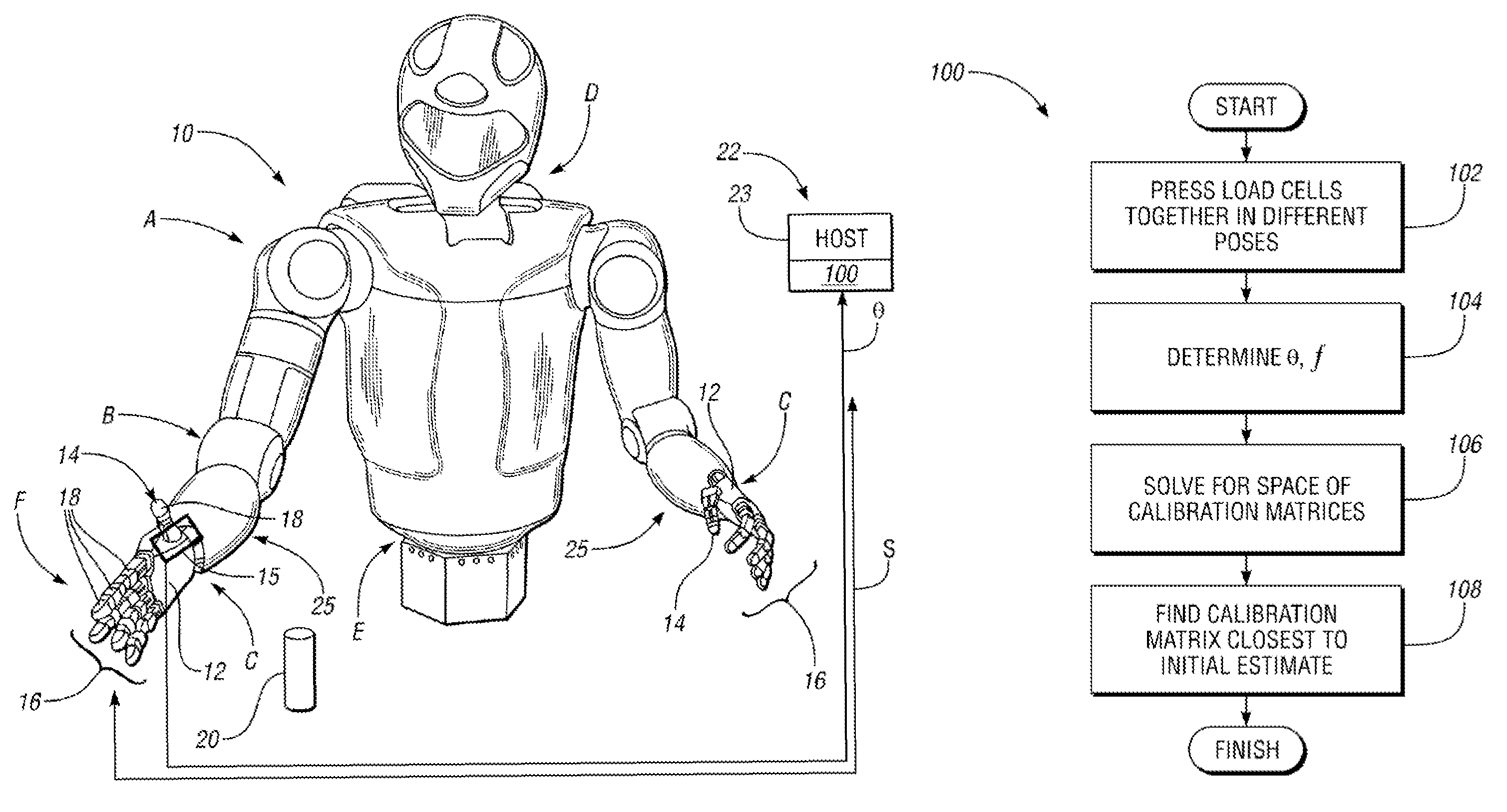
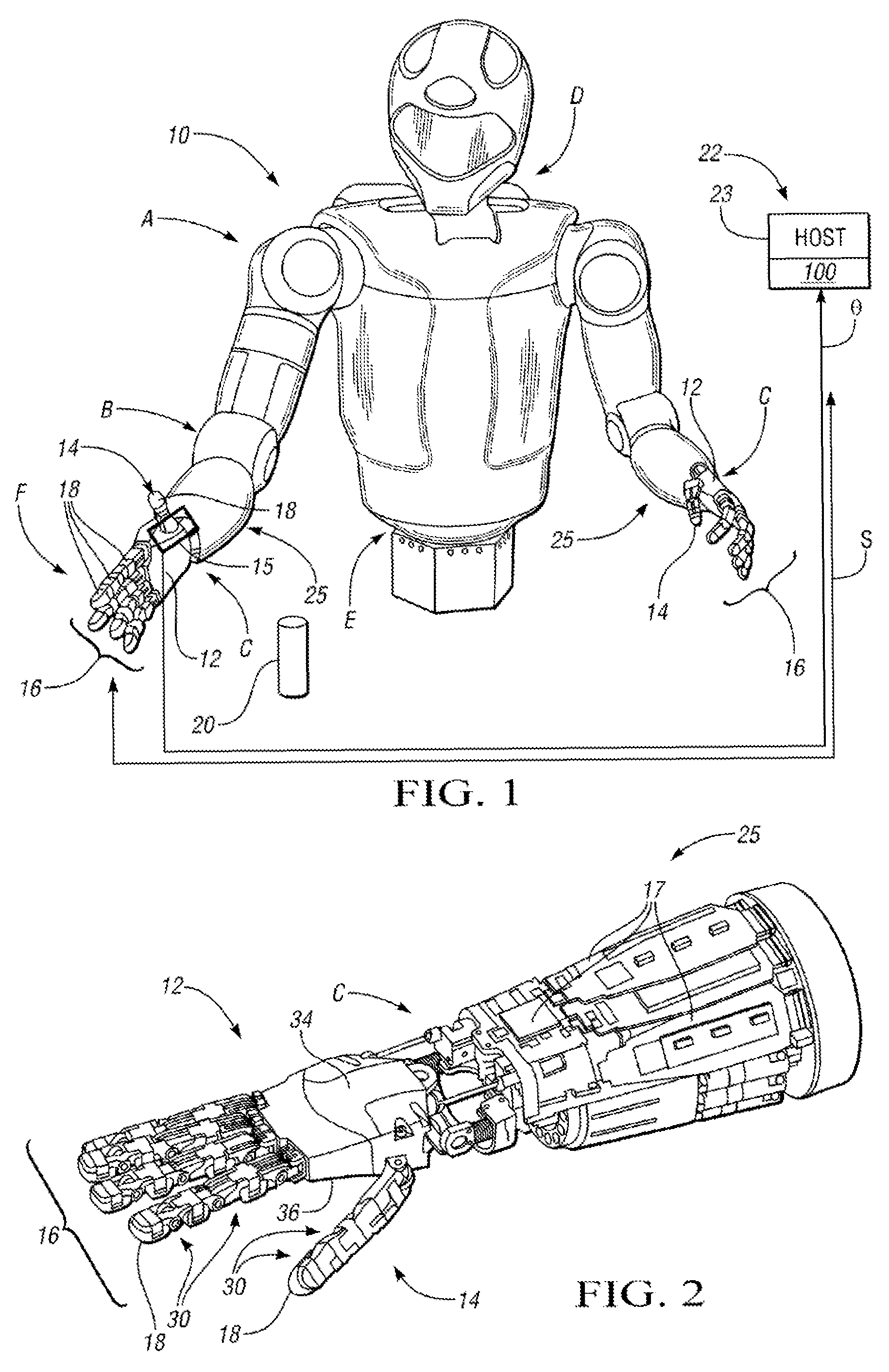
[0015]With reference to the drawings, wherein like reference numbers refer to the same or similar components throughout the several views, and beginning with FIG. 1, a dexterous robot 10 is adapted to perform one or more automated tasks. The robot 10 is configured with independently and / or interdependently-moveable motor-driven robotic joints, such as but not limited to a shoulder joint, the position of which is generally indicated by arrow A. The robot 10 may also include an elbow joint (arrow B), a wrist joint (arrow C), a neck joint (arrow D), a waist joint (arrow E), and finger joints (arrow F). Each of the joints includes one or more joint angle sensors 15 adapted for measuring joint angles (A), and for relaying these angular measurements to a host machine (HOST) 22 for processing via a sensor calibration algorithm 100 as explained below.

[0016]The robot 10 includes a lower arm assembly 25 having one or more anthropomorphic hands 12. Each hand 12 includes an opposable thumb 14 a...


PUM


Abstract

A robotic system includes a dexterous robot having robotic joints, angle sensors adapted for measuring joint angles at a corresponding one of the joints, load cells for measuring a set of strain values imparted to a corresponding one of the load cells during a predetermined pose of the robot, and a host machine. The host machine is electrically connected to the load cells and angle sensors, and receives the joint angle values and strain values during the predetermined pose. The robot presses together mating pairs of load cells to form the poses. The host machine executes an algorithm to process the joint angles and strain values, and from the set of all calibration matrices that minimize error in force balance equations, selects the set of calibration matrices that is closest in a value to a pre-specified value. A method for calibrating the load cells via the algorithm is also provided.

Description

STATEMENT REGARDING FEDERALLY SPONSORED RESEARCH OR DEVELOPMENT[0001]This invention was made with government support under NASA Space Act Agreement number SAA-AT-07-003. The government may have certain rights in the invention.TECHNICAL FIELD[0002]The present invention relates to the calibration of strain sensors or load cells of the type used by a dexterous robot.BACKGROUND OF THE INVENTION[0003]Robots are able to grasp and manipulate objects using a series of linkages, which in turn are interconnected via one or more motor-driven robotic joints. End-effectors are the particular linkages used to perform a given task at hand, e.g., the grasping of a work tool or other object. Humanoid robots are a dexterous type of robot having an approximately human structure or appearance, whether a full body, a torso, a hand, or another appendage. The structural complexity of a dexterous robot is largely dependent upon the complexity of the commanded work task.[0004]Due to the wide spectrum of wor...

Claims


Application Information

Patent Timeline
Patent Type & Authority Patents(United States)
IPC IPC(8): G05B19/04
CPCB25J9/1692G01L5/226B25J15/0009G01L25/00G05B2219/39024G05B2219/40618
Inventor WAMPLER, II, CHARLES W.PLATT, JR., ROBERT J.
Owner GM GLOBAL TECH OPERATIONS LLC
Learn More