
Carbon monoxide and smoke detectors having distinct alarm indications and a test button that indicates improper operation

a technology of carbon monoxide and smoke detectors, which is applied in the direction of fire alarms, fire alarm smoke/gas actuation, signalling systems, etc., can solve the problems of typical detectors, their sensitivity to temperature, and the need for complicated control electronics of solid-state receivers

Active Publication Date: 2012-07-31
GENTEX CORP
View PDF188 Cites 45 Cited by
  • Summary
  • Abstract
  • Description
  • Claims
  • Application Information

AI Technical Summary

Benefits of technology

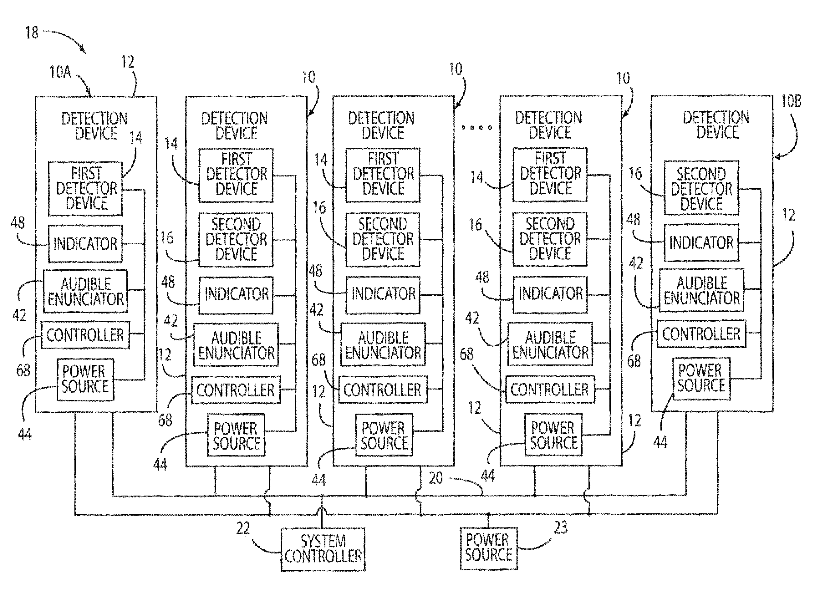
The present invention provides a detection device that can detect both smoke particles and gas particles, and an audible enunciator that can emit different sounds based on the type of particles detected. The detection device can also be connected to other detection devices using a conductor, allowing signals to be communicated between them. Additionally, an indicator device can be included that can monitor the operating condition of the detection device and emit light for diagnostic purposes. These features make the detection device more versatile and efficient in detecting different types of particles.

Problems solved by technology

One difficulty with solid-state receivers is their sensitivity to temperature.
Typical detectors also require complicated control electronics to detect the light level including analog amplifiers, filters, comparators, and the like.
These components may be expensive if precision is required, may require adjustment when the smoke detector is manufactured, and may exhibit parameter value drift over time.
Further, detection systems, which include several such smoke detectors, typically only detect smoke.
However, the additional detectors typically result in an additional device in the system that has to be mounted on a building structure (e.g., a wall or ceiling) in addition to the smoke detector.

Method used


Image

  • Carbon monoxide and smoke detectors having distinct alarm indications and a test button that indicates improper operation
  • Carbon monoxide and smoke detectors having distinct alarm indications and a test button that indicates improper operation
  • Carbon monoxide and smoke detectors having distinct alarm indications and a test button that indicates improper operation

Examples


Embodiment Construction

[0022]Reference will now be made in detail to present preferred embodiments of the invention, examples of which are illustrated in the accompanying drawings. Wherever possible, the same reference numerals will be used throughout the drawings to refer to the same or like parts.

[0023]For purposes of description herein, the terms “upper,”“lower,”“right,”“left,”“rear,”“front,”“vertical,”“horizontal,”“top,”“bottom,” and derivatives thereof shall relate to the invention as shown in the drawings. However, it is to be understood that the invention may assume various alternative orientations, except where expressly specified to the contrary. It is also to be understood that the specific device illustrated in the attached drawings and described in the following specification is simply an exemplary embodiment of the inventive concepts defined in the appended claims. Hence, specific dimensions, proportions, and other physical characteristics relating to the embodiment disclosed herein are not t...


PUM


Abstract

A detection device and detection device system are provided, wherein the detection device includes a housing, a first detector device and a second detector device. The first detector device is configured to detect at least one smoke particle. A second detector device configured to detect at least one gas particle, wherein the first detector device and the second detector device are substantially enclosed in the housing. The detection device further includes an audible enunciator configured to emit an audible noise when at least one of the first and second detector devices detect at least one smoke and gas particle, and a test button, wherein the audible enunciator emits an audible sound when the detection device is operating improperly and the test button is activated.

Description

FIELD OF THE INVENTION[0001]The present invention generally relates to a device for detecting a smoke particle and a gas particle, and more particularly, to a system including a device that detects a smoke particle and a carbon monoxide particle.BACKGROUND OF THE INVENTION[0002]Generally, smoke detectors detect the presence of smoke particles as an early indication of fire. Smoke detectors are typically used in closed structures such as houses, hotels, motels, dormitory rooms, factories, offices, shops, ships, aircraft, and the like. Smoke detectors may include a chamber that admits a test atmosphere while blocking ambient light. A light receiver within the chamber can receive a level of light from an emitter within the chamber, which light level is indicative of the amount of smoke contained in the test atmosphere.[0003]Several types of fires can generally be detected. A first type is a slow, smoldering fire that produces a “gray” smoke containing generally large particles, which m...

Claims


Application Information

Patent Timeline
Patent Type & Authority Patents(United States)
IPC IPC(8): G08B21/00
CPCG08B3/10G08B5/36G08B17/10G08B17/103G08B17/117G08B29/145G08B17/113G08B29/185
Inventor PATTOK, GREG R.FISH, JR., RICHARD T.EDWARDS, SCOTT R.TUTTLE, DARIN D.STIRLING, CHRISTOPHER D.
Owner GENTEX CORP
Learn More