
Anti-clogging drainage inlet

a drainage inlet and anti-clogging technology, applied in the direction of multi-stage water/sewage treatment, separation process, ways, etc., can solve the problems of relatively small debris pieces and water in the container, and achieve the effect of reducing the weight of the container, and raising the gra

Inactive Publication Date: 2012-07-24
MONDSCHEIN BRIAN E +1
View PDF18 Cites 17 Cited by
  • Summary
  • Abstract
  • Description
  • Claims
  • Application Information

AI Technical Summary

Benefits of technology

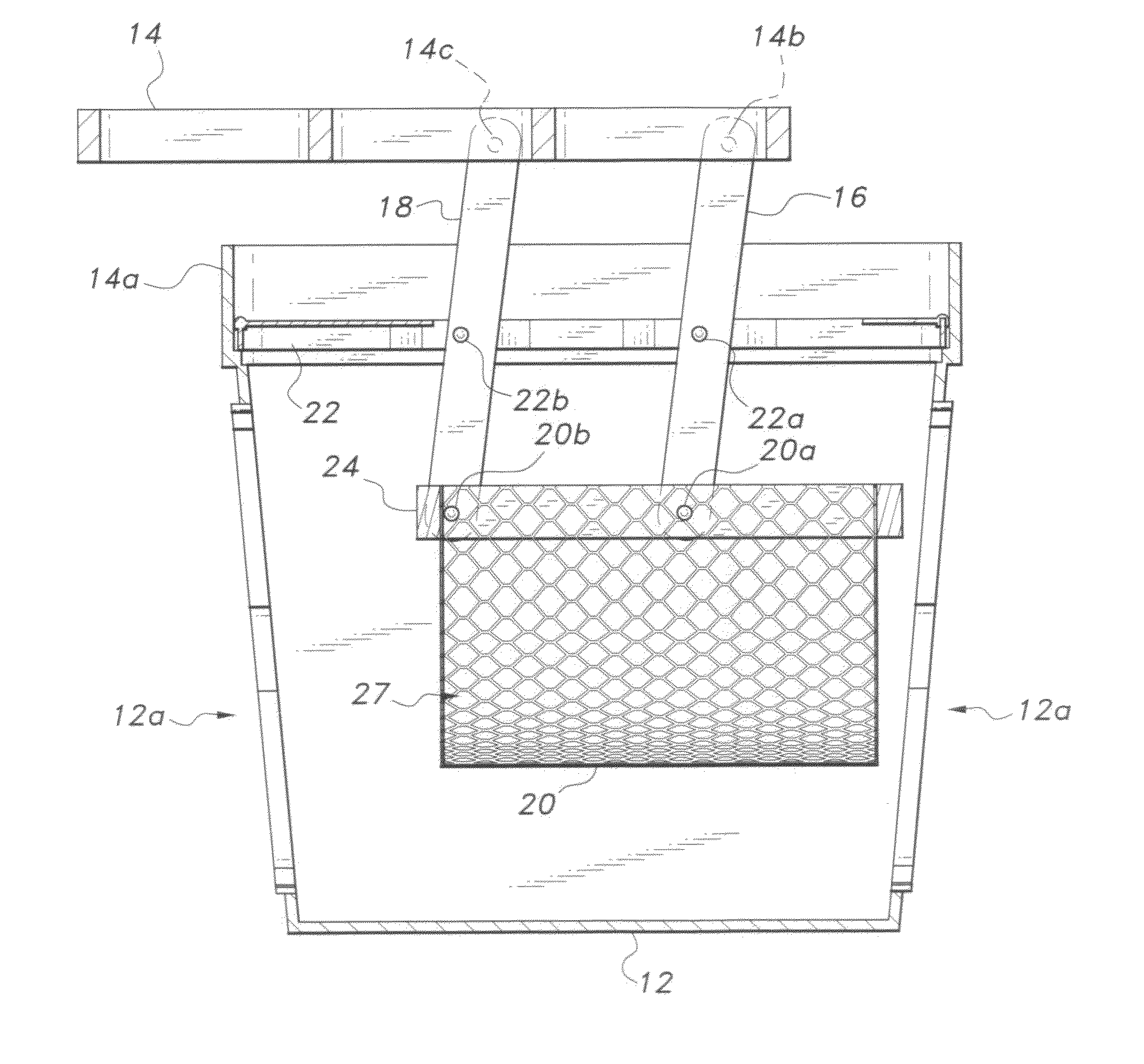
[0006]In its flush position, the grate functions to prevent relatively large pieces of trash and debris from entering the drainage box and clogging the overall drainage system. During periods of excessive flow, the container will fill with water and relatively small pieces of debris. The increased weight will cause the linkage system to pivot and raise the grate. As water flows through the perforated material, the weight of the container is reduced and the grate will return to its flush position. However, if the amount of debris in the container is of an amount to maintain the pivoting weight, the grate will remain in a raised position as an indication that the container should be cleaned out.
[0007]Accordingly, the anti-clogging drainage inlet is conveniently adaptable to existing drainage systems. The invention is rugged in design and easy to maintain. The invention provides for improved elements thereof in an arrangement for the purposes described that are inexpensive, dependable and fully effective in accomplishing their intended purposes.

Problems solved by technology

During periods of excessive flow, the container will fill with water and relatively small pieces of debris.
The increased weight will cause the linkage system to pivot and raise the grate.

Method used


Image

  • Anti-clogging drainage inlet
  • Anti-clogging drainage inlet
  • Anti-clogging drainage inlet

Examples


Embodiment Construction

[0015]Referring to FIGS. 1-4 wherein the anti-clogging drainage inlet 10 is disposed atop a conventional drainage box 12. The box 12 is positioned beneath the surface of the ground G of a lawn or field. The drainage box 12 has openings 12a therein for receiving a drain duct (shown in phantom lines). The drainage inlet 10 is configured to nest in the drainage box 12.

[0016]The drainage inlet 10 comprises a grate member 14 configured as an open grid. A linkage system is attached to the grate 14. The linkage system comprises a first pair of legs 16 having proximate ends pivotally attached at 14b adjacent to a first end of the grate 14 at each side thereof (only one leg 16 is shown in the section views of FIGS. 3 and 4). The distal ends of first legs 16 are pivotally attached to a lower positioned rectangular frame member 24 at 20a. A second pair of legs 18 has proximate ends pivotally attached to the grate 14 at 14c. The distal ends of the legs 18 are pivotally attached to lower positio...


PUM

PropertyMeasurementUnit
sizeaaaaaaaaaa
weightaaaaaaaaaa
lengthsaaaaaaaaaa

Abstract

The anti-clogging drainage inlet is adapted for use in lawn or field environments that require drainage systems to prevent flooding or unwanted pooling during periods of rain. The inlet includes a grate mounted to a rectangular frame. The frame and the grate are adapted to be positioned in the opening of a conventional drainage box in a manner that the top surface of the grate is flush with the surface of the lawn or field. A linkage system is mounted to the frame and grate and operates to raise the grate from its flush position. The linkage system includes a container positioned below the grate and within the drainage box.

Description

BACKGROUND OF THE INVENTION[0001]1. Field of the Invention[0002]The present invention generally relates to filtering assemblies, particularly for landscaping area drains, and more particularly to an anti-clogging drainage inlet.[0003]2. Description of the Related Art[0004]Providing drainage assemblies for lawn or field areas has heretofore presented problems in that the drainage assemblies frequently become clogged with debris (leaves, dirt, trash, etc.). The clogged drain prevents proper water run-off causing pooling or flooding in the lawn or field surrounding the assembly. Such pooling and / or flooding can cause damage to the lawn or field and to structures that may be positioned thereon. The art would certainly welcome a drainage assembly that could withstand an exceptional flow of debris, yet still function to reliably drain water from surrounding areas. Thus the anti-clogging drainage inlet solving the aforementioned problems is desired.SUMMARY OF THE INVENTION[0005]The anti-cl...

Claims


Application Information

Patent Timeline
Patent Type & Authority Patents(United States)
IPC IPC(8): E03F5/06
CPCE03F5/0404E03F5/06
Inventor MONDSCHEIN, BRIAN E.MAGRATH, MARK J.
Owner MONDSCHEIN BRIAN E
Learn More