Photographing device in particular for video surveillance and working methods of same

a technology for video surveillance and photographing modules, applied in the field of photography, can solve the problems of limiting the possibility of rotation of the photographing module to the twisting capacity of said wires, and not providing a solution to data management,

Inactive Publication Date: 2012-05-01
MARDEL IMAGE
View PDF19 Cites 17 Cited by
  • Summary
  • Abstract
  • Description
  • Claims
  • Application Information

AI Technical Summary

Benefits of technology

[0018]This protective housing is therefore capable of rotating fully according to both a horizontal axis and a vertical axis. The camera has full rotational mobility according to two axes. Its visual field is limited only by the presence of the plate, of which the volume does not prevent the objective of the camera from going beyond the horizontal. Indeed, said plate is advantageously preformed so as not to form an obstacle when the objective of the camera exceeds the horizontal plane. The mobility enables the problems of speed of movement and difficulty of installation to be solved. It is thus no longer necessary to study the camera positioning very precisely in particular according to all of the ground slopes. The device can therefore be arranged right side up or upside down. This device also has no dome and is therefore not equipped with a dome support, which limits the field of view of the device according to an angle of 180° above or below the dome support according to its arrangement.
[0019]To make it possible to propose additional functionalities, the protective housing of the device of the invention can receive a plurality of photographing means of the same technology. This feature makes it possible to envisage instantaneous perimetric photographing without requiring a rotational movement. Similarly, according to another feature, the protective housing can receive a plurality of photographing means of different technologies, such as, for example, infrared or ultraviolet viewing means providing, for a single device, a plurality of viewing solutions.
[0023]According to another particularly advantageous feature of the invention, said protective housing includes a window in front of which the objective of the photographing means is installed, which window is closed by a plate of transparent material. The use of a planar element to protect the objective of the photographing means avoids the disadvantages of the prior art, namely focusing on the protective spherical portions.
[0024]This feature makes it possible to envisage photographing means with zooming capabilities that are largely superior to what is normally provided for dome-type devices. Thus the zooming capabilities are limited only by the current technological limitations of on-board photographing devices. In addition, the device of the invention has been designed to receive the most recent photographing means, of which the zooming and precision capabilities are capable of increasing. Thus, according to another particularly advantageous feature, the zooming capability of the photographing means is at least, if not much greater than, twenty-five.

Problems solved by technology

The applicant has noted that the existing solutions have a number of problems, including the following:cameras placed inside a protection dome have a reduced zooming capacity due to the presence of said dome.
Indeed, beyond a certain focal distance, the objective of the camera will focus from the spherical cap of the concave surface of the dome;the cameras used on turrets are either stationary or move very slowly;the cameras used in domes cannot provide a view beyond the horizontal plane above or below which they are arranged;the effective use of the domes and cameras in general requires regular cleaning of their lens shields (planar surface) for turrets or their spherical cap for domes;cameras in domes or installed on turrets require a specialised installer for their installation.
This device has the disadvantage of not providing a solution to the management of data concerning the real positioning of the camera on its rotation axes.
In addition, the use of hinges as wire passage means has the disadvantage of limiting the possibilities for rotation of the photographing modules to the twisting capacities of said wires.
In addition, the photographing housing does not have means for protecting the objective of the camera that it contains.
But the diameter of the field of view provided by such a device remains limited to said zooming capabilities.
Another disadvantage noted in the devices of the prior art concerns the limitation of the number and type of photographing means implemented.

Method used


Image

  • Photographing device in particular for video surveillance and working methods of same
  • Photographing device in particular for video surveillance and working methods of same
  • Photographing device in particular for video surveillance and working methods of same

Examples


Embodiment Construction

[0015]On the basis of this prior art, the applicant has conducted research in order to design a device implementing photographing means or a camera, in particular for video surveillance purposes, overcoming the disadvantages of the prior art.

[0016]The applicant focused on trying to achieve the various advantages seen separately in the devices of the prior art.

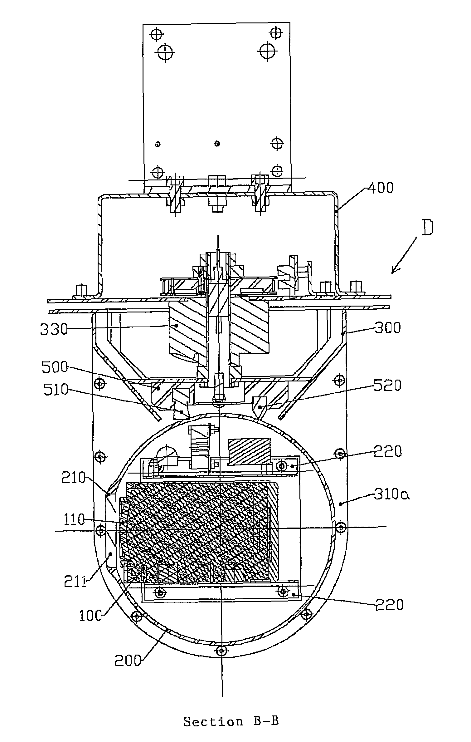
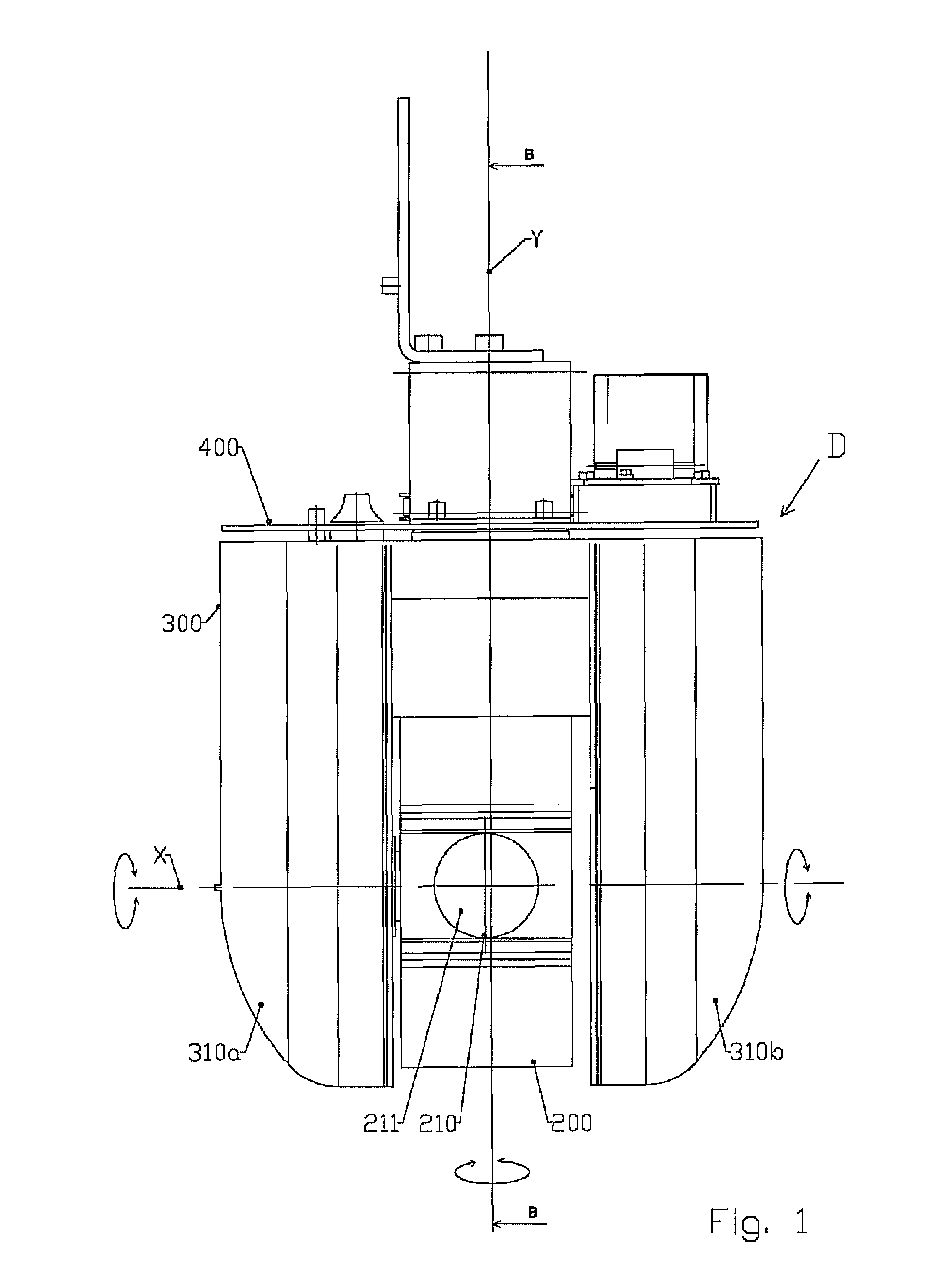
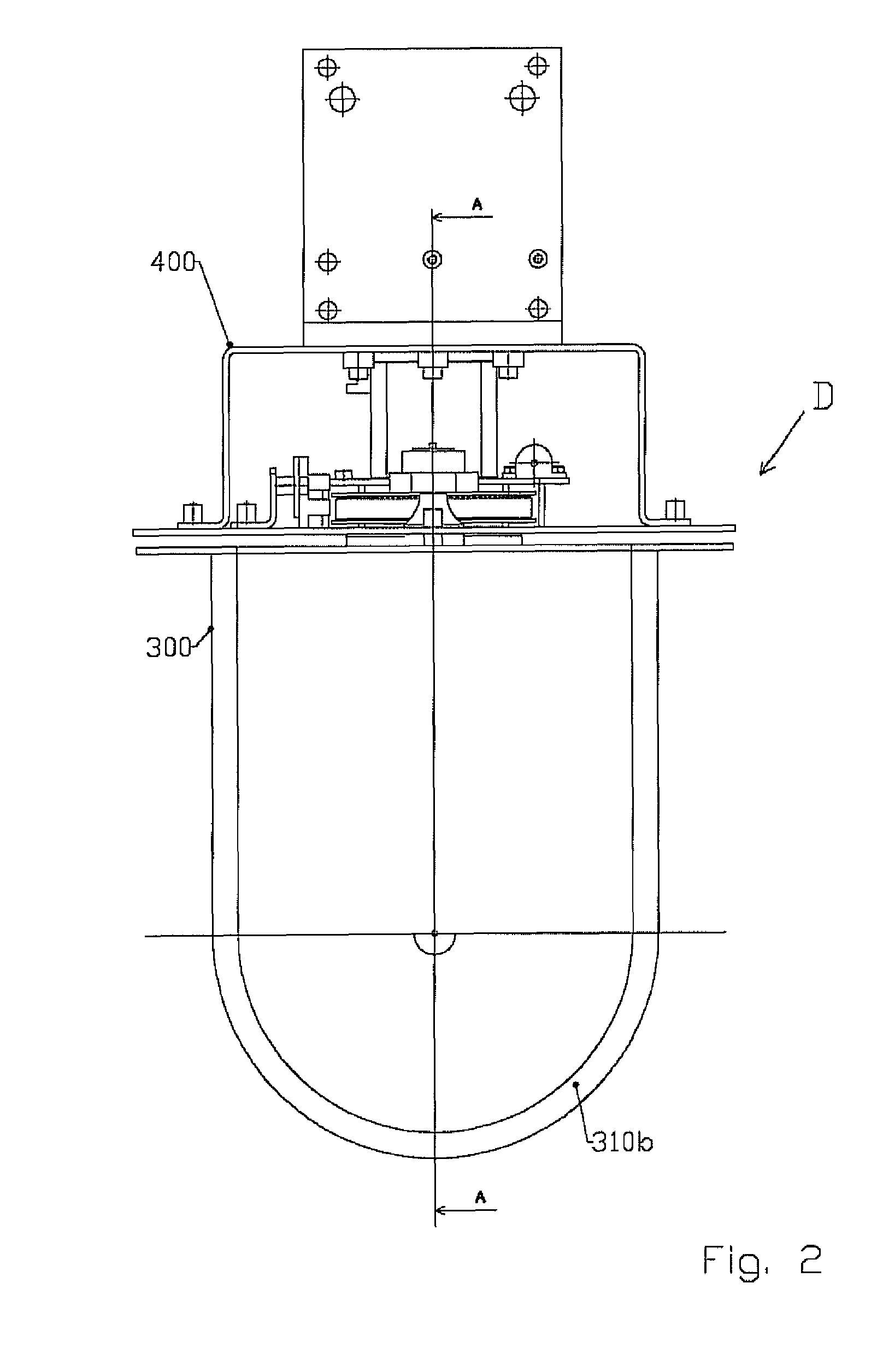
[0017]This research led to the design of a device providing the control and movement of at least one photographing means, remarkable in that it is constituted by a housing that, forming a protective chamber around at least one photographing means, is mounted mobile in rotation along a first axis with respect to at least one arm integrated with a plate that is itself mounted mobile in rotation along a second axis perpendicular to the first, with respect to a stationary base, wherein the two rotation movements occur over three hundred and sixty degrees without stopping, with the arrangement and size of the photographing means wit...


PUM


Abstract

Disclosed is a device providing the control and movement of a camera. The device includes a housing configured to form a protective chamber around the camera, the housing being mounted mobile in rotation along a first axis with respect to an arm. The device further includes a first slip ring between the housing and the arm, and a second slip ring. Power for the camera is transmitted in the first and second slip ring.

Description

TECHNICAL FIELD OF THE INVENTION[0001]This invention relates to the field of photographing using or not using a video technique, and in particular to adaptations making it possible to provide the operation of a mobile camera under the best conditions.DESCRIPTION OF THE PRIOR ART[0002]The prior art discloses a number of solutions for moving a camera, in particular a surveillance camera. These solutions can be classified into two categories: turrets and domes.[0003]The applicant has noted that the existing solutions have a number of problems, including the following:[0004]cameras placed inside a protection dome have a reduced zooming capacity due to the presence of said dome. Indeed, beyond a certain focal distance, the objective of the camera will focus from the spherical cap of the concave surface of the dome;[0005]the cameras used on turrets are either stationary or move very slowly;[0006]the cameras used in domes cannot provide a view beyond the horizontal plane above or below whi...

Claims


Application Information

Patent Timeline
Patent Type & Authority Patents(United States)
IPC IPC(8): G03B17/00
CPCG03B15/00
Inventor MARTOS, FRANCOIS
Owner MARDEL IMAGE
Why Eureka
Try Eureka