Multifunction display and operating device in a motor vehicle

a multi-functional display and operating device technology, applied in the direction of emergency actuators, instruments, cathode-ray tube indicators, etc., can solve the problems of skewing the stroke key, affecting the operation of the display device, so as to achieve the effect of improving operability

Active Publication Date: 2012-04-10
VOLKSWAGEN AG +1
View PDF13 Cites 0 Cited by
  • Summary
  • Abstract
  • Description
  • Claims
  • Application Information

AI Technical Summary

Benefits of technology

[0007]Example embodiments of the present invention provide a multifunctional display and operating device for which a better operability is achieved, in particular, that smaller gap clearances may be implemented and as large a proportion as possible of the operating surface is able to be illuminated.
[0008]In a multifunctional display and operating device of the type mentioned at the outset, in order to do this, it is provided that the operating elements are arranged as keys which are able to be pivoted in each case about a rotational axis extending in or at an end region of the keys parallel to the display surface. The arrangement of the operating elements as rotatable keys provides that the mechanical degrees of freedom of the operating element are reduced during operation as compared to an operating element arranged as a stroke key. This makes it possible to select a gap dimension to be smaller, for the same size of operating surface, as in the case of a stroke key of conventional arrangements. This makes it possible to position the operating elements in a manner of closer vicinity to one another. In addition, it will be more difficult for dust and dirt to enter into the hollow space between the key and a panel, or a key comb that surrounds the key. This lessens the soiling of the display and operating device, which could otherwise impair the functional suitability. The term rotational axis is used here in each case only for a virtual geometric axis, about which a rotational movement is executed or is able to be executed. The term rotational axis will not be used to designate an axis arranged in material. Because of the restriction of the degrees of freedom of the operating element, a reliable triggering of a switching process is able to be ensured using only one switching element at each operation. By contrast to stroke keys as in conventional arrangements, which include two switching elements or one switching element having two switching devices, an electronic circuit may thus be simplified and switching elements and / or switching devices may be dispensed with. Consequently, a more cost-effective and a simpler design of a multifunctional display and operating devices comes about, all things considered.
[0010]In order to provide as good an illumination as possible of an operating surface of the keys, it may be provided to create a hollow space under one-half of the keys on the inside of the multifunctional display and operating device. A switching element triggered by operating a key may therefore be positioned at a distance from the operating surface, below the key. Improved illumination of the operating surface of the key may thus be achieved for a key where the keys include a push rod, projecting from the side opposite the operating surface, whose one end interacts with a switching element of a switch mat when the operating element is operated, the push rod being arranged at an opposite end region of the key. If a connecting line between the end region and the opposite end region is designated as the longitudinal axis, then the operating surface is able to be illuminated in a large region along the longitudinal axis, which raises operability and operating convenience in the dark. Even the fact that the keys are pivotable at the one end region, about the rotational axis, already leads to being able to save a plurality of guides at the side of the key facing away from the operating surface. This enlarges the area of the operating surface that is able to be illuminated.
[0011]The operating convenience is, moreover, improved in an arrangement in which the keys each include a key cap made of a transparent base material which is lacquered at least at the operating surface, the lacquering being interrupted to form pictograms, symbols and / or characters. A representation of a fixed functional assignment to the operating elements may be made via the legend of the key caps. It is also possible in this manner only to make clear a preferred allocation. The enlarged region that is able to be illuminated in the case of the keys hereof, compared to the usual stroke keys, makes it possible to illuminate more or more complicated characters, symbols and / or pictograms, or larger characters and larger symbols or more complicated pictograms on the operating surface. This makes it possible to put whole words in a readable size on the operating surface, and not only to use abbreviations.
[0015]The operating possibilities of an operating device are greatly increased by stating an allocation of the operating elements to the functions via the displayed information. This makes it possible, using characters or symbols or pictograms, to allocate different functions, independently of a legend on the keys.
[0016]A keying selection of the operating elements by a user, that is based purely on haptic impressions, is made possible in that the operating surface, at the opposite end region in an unoperated setting, as seen from the operating side, projects from a panel frame or a key comb. An excessive force action, which may lead to damage of the switching element, is able to be avoided exemplary embodiments, in which the operating surface at the opposite end region, in response to the excursion at which the switching process is triggered, closes level with a panel frame or key frame surrounding the key, or, as seen from the operating side, enters into the panel frame or key comb, and, in a non-excursion state, projects in an elevated state from the panel frame or the key comb. As soon as the key has traveled out to the stop point at which the switching element is operated, a finger of the user operating the key pushes at least partially against the panel or the key comb, in the case of a suitable dimensioning of the operating surface. Because of this, a part of the force is diverted to the panel or the key comb, so that an excessive force action is avoided. This particularly also applies if the operating elements are arranged in an area at which the user may unintentionally knock against the operating elements with some object. In such a case, in particular, it may be provided to cushion the enormously great forces using the panel frame or the key comb.

Problems solved by technology

If the distances between the gaps are selected to be too slight, when the up-and-down motions of the keys are executed, the keys may become skewed or jammed.
The reason is that otherwise, in response to an operating force that is not impinging centrally on the stroke key, skewing of the stroke key may take place and the reliable triggering of a switching process is not securely ensured in response to each operation.
In addition, it will be more difficult for dust and dirt to enter into the hollow space between the key and a panel, or a key comb that surrounds the key.
This lessens the soiling of the display and operating device, which could otherwise impair the functional suitability.
In certain conventional arrangements, these are arranged such that, when a so-called pressure point is passed, an opposing force of the switching element on the key decreases relatively abruptly, and simultaneously to this, a clicking noise is generated.
Some users find this unpleasant.
This particularly also applies if the operating elements are arranged in an area at which the user may unintentionally knock against the operating elements with some object.

Method used


Image

  • Multifunction display and operating device in a motor vehicle
  • Multifunction display and operating device in a motor vehicle
  • Multifunction display and operating device in a motor vehicle

Examples


Embodiment Construction

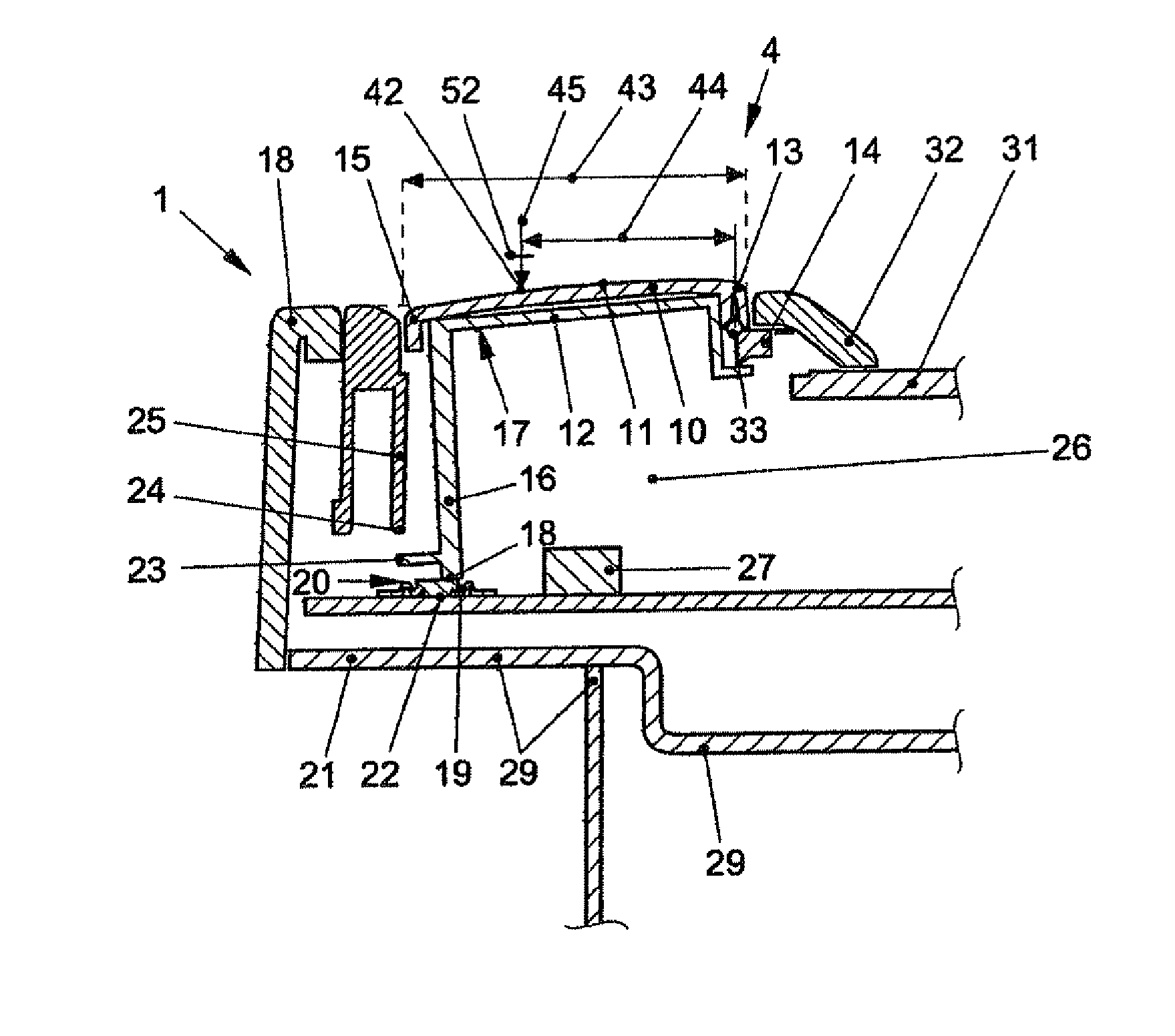
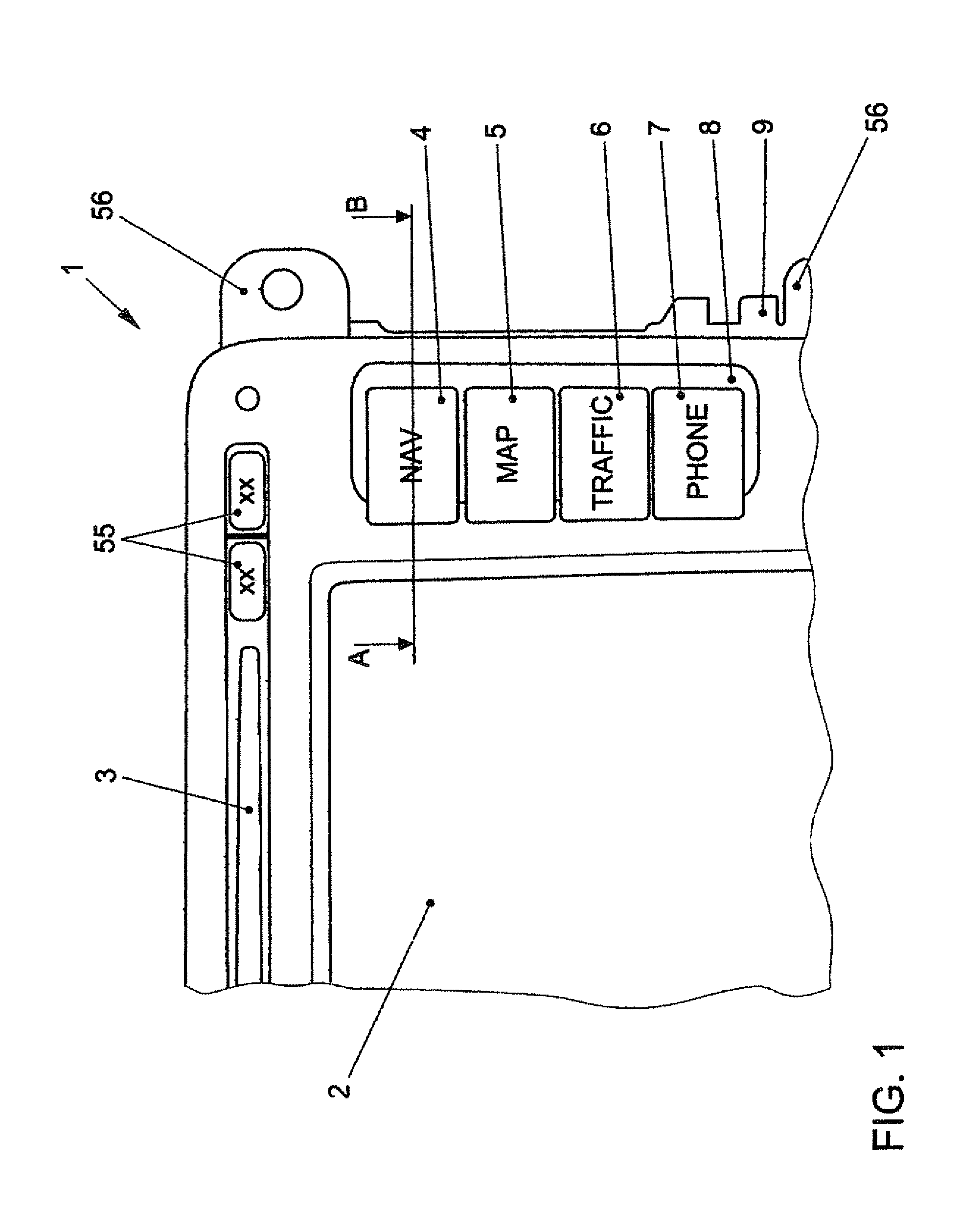
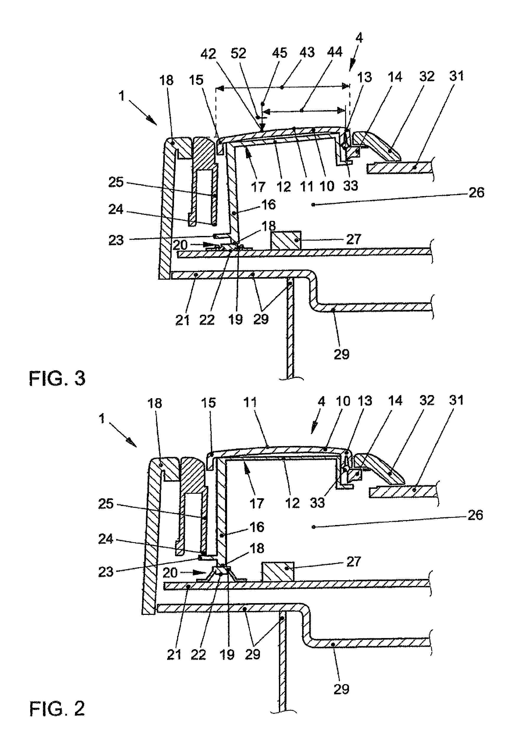
[0022]FIG. 1 is a partial top view of a multifunctional display and operating device 1. Multifunctional display and operating device 1 is arranged as a multimedia unit and navigational unit. It includes a display field 2, on which information is shown. In an upper area a slot 3 may be seen, in which storage media, especially optical storage media, such as CD's, DVD's, etc., are able to be introduced. Next to display field 2, operating elements 4-7 are situated. Operating elements 4-7 are arranged as keys that are rotatable about a rotational axis that runs parallel to the plane of the drawing. Operating elements 4-7 are surrounded by a key comb 8. The gap dimensions between operating elements 4-7 and key comb 8 may be selected to be smaller than in the case of an arrangement in which the operating elements are developed as stroke keys. Key comb 8 is fitted into a housing panel 9 of multifunctional display and operating device 1, e.g., using a snap-in connection. In order to achieve ...


PUM


Abstract

A multifunctional display and operating device in a motor vehicle includes a display field for displaying information, and, situated adjacent to the display field, includes operating elements for selecting functions, the operating elements arranged as keys which are each pivotable about a rotational axis extending in, or at an end region of the keys parallel to a surface of the display field.

Description

[0001]This application is a 371 of PCT / EP07 / 00961, filed Feb. 5, 2007.FIELD OF THE INVENTION[0002]The present invention relates to a multifunctional display and operating device in a motor vehicle, having a display field for displaying information, and, adjacent to the display field, operating elements are situated for selecting functions.BACKGROUND INFORMATION[0003]Multifunctional display and operating devices are used more and more these days in motor vehicles. On the one hand, they are used for displaying information on the state of the motor vehicle. On the other hand, these multifunctional display and operating devices are used to control vehicle systems, such as a navigational system or an automobile radio. A fixed function may be assigned to the individual operating elements. However, in certain conventional arrangements, multifunctional display and operating devices are preferred in which information is shown in the display field which indicate functional directions to the i...

Claims


Application Information

Patent Timeline
Patent Type & Authority Patents(United States)
IPC IPC(8): G06F3/02
CPCB60K37/06H01H21/24H01H2221/016
Inventor SCHWARZ, OLAFWOIKE, RUDIGERSEIFERT, JORGSCHMIDT, REINER
Owner VOLKSWAGEN AG
Why Eureka
Try Eureka