
Bi-material prosthesis component

a technology of prosthesis and bi-materials, applied in the field of joint replacement surgery, can solve the problems of extending affecting the service life of hip prosthesis, and releasing particulate material into the patient's body

Active Publication Date: 2012-03-27
ZIMMER INC
View PDF25 Cites 4 Cited by
  • Summary
  • Abstract
  • Description
  • Claims
  • Application Information

AI Technical Summary

Benefits of technology

[0011]In another aspect, the coating may be harder than the interior wall of the cup. For example, the coating may be harder by forming the interior wall of the cup from a metallic material and forming the coating from a ceramic material.

Problems solved by technology

In addition to increasing longevity, minimizing wear of the hip prosthesis components also curtails the potential release of particulate material from prosthetic components into the patient's body.
These disparate material properties may prolong the service life of the hip prosthesis.

Method used


Image

  • Bi-material prosthesis component
  • Bi-material prosthesis component
  • Bi-material prosthesis component

Examples


Embodiment Construction

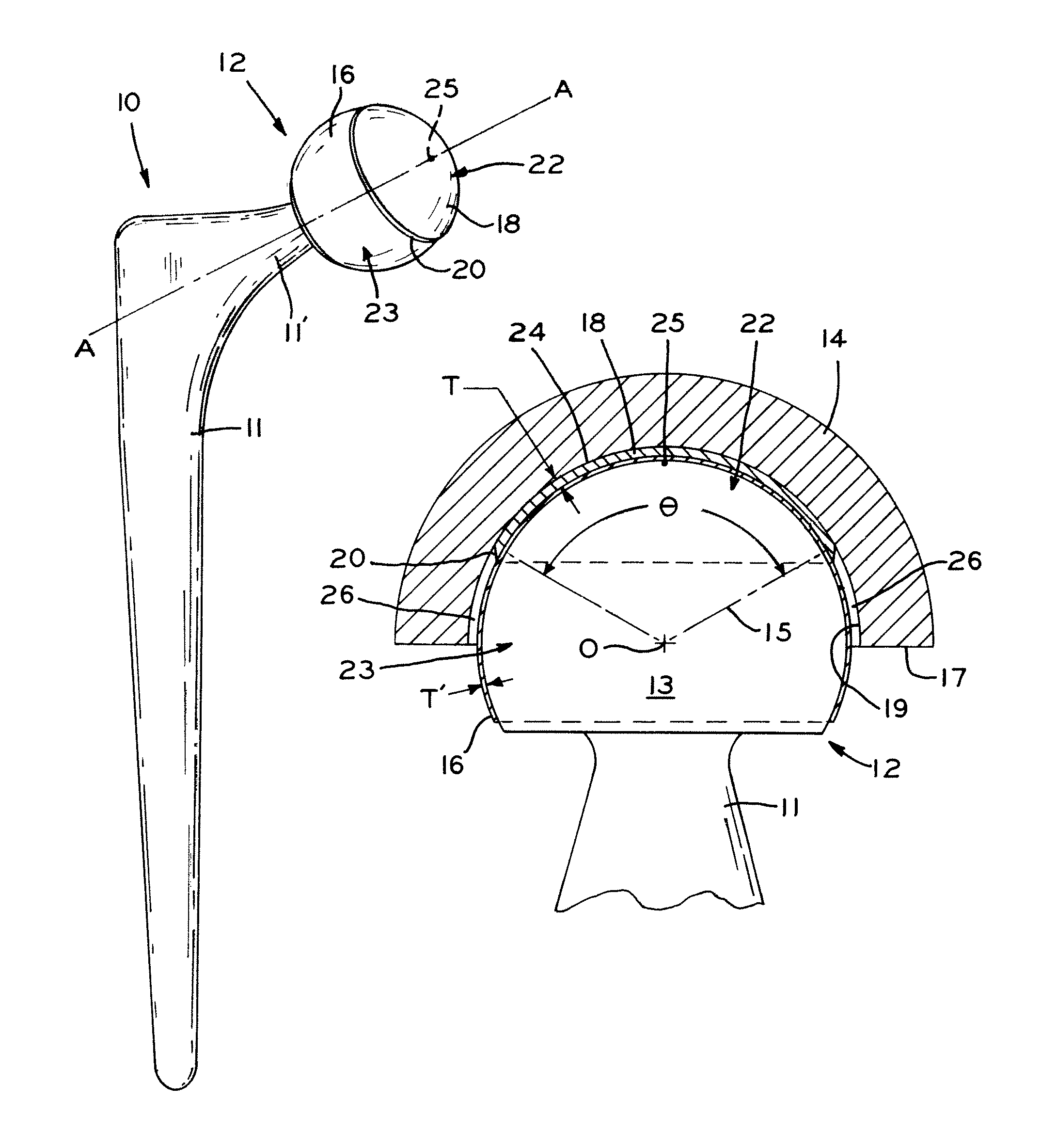
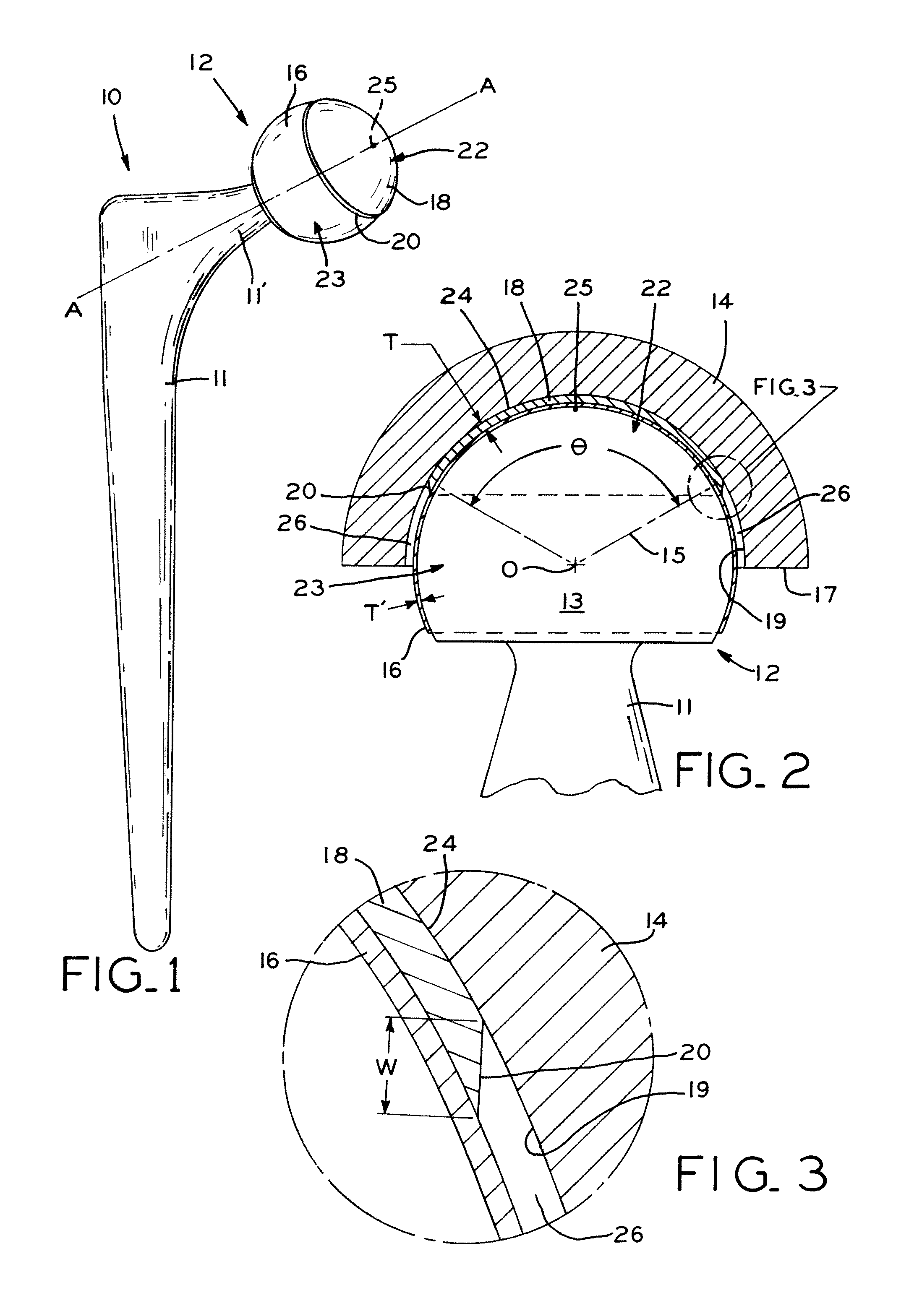
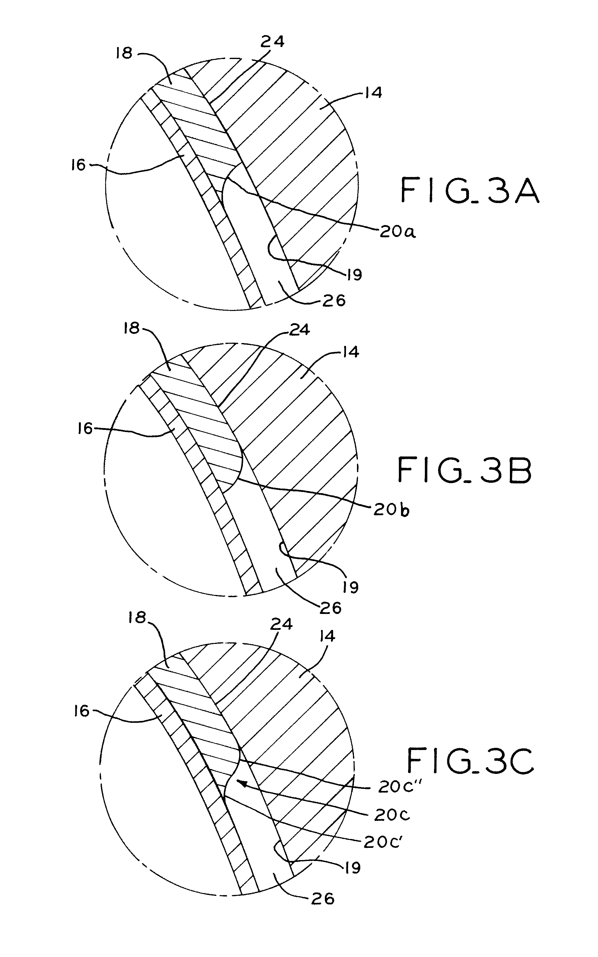
[0039]Referring to FIG. 1, prosthesis 10 includes femoral component 11 with femoral head 12 attached at a proximal end thereof. Femoral head 12 includes substrate 13 (FIG. 2) including polar region 22 forming a “cap” on femoral head 12 proximate pole 25 (FIG. 2, discussed below) and equatorial region 23 forming an annular “band” disposed between femoral component 11 and polar region 22. Substrate 13 is made of a metallic material, such as titanium, titanium alloys, and other alloys including cobalt chromium and zirconium materials such as cobalt chrome molybdenum, for example. Femoral head 12 also includes polar coating 18 made of a ceramic material, with coating 18 disposed at polar region 22 of femoral head 12. An inner, optional coating 16 may extend over a portion of an outer surface of femoral head 12, such as over more than half of femoral head 12. Polar coating 18 is disposed at polar region 22 of femoral head 12 and extends over less than half of femoral head 12, as discusse...


PUM

PropertyMeasurementUnit
thicknessaaaaaaaaaa
thicknessaaaaaaaaaa
radiusaaaaaaaaaa

Abstract

A prosthesis has prosthetic components principally comprising metallic materials, in which a portion of an articular interface between respective components is a metallic-nonmetallic interface. At least a portion of the articular surface of a femoral head may include a ceramic material defining an articulation zone, such as at a polar region of the femoral head, so that the ceramic articulates with a metallic acetabular liner. The area covered by the ceramic may be engineered to optimize the contact conditions between the femoral head and the acetabular liner, such as by providing two clearances therebetween. A relatively smaller, polar articulation clearance is defined by the gap between the ceramic coating and the metallic acetabular liner. A relatively larger, equatorial non-articulation clearance between the femoral head and the acetabular liner is defined by the gap between the portion of the femoral head not covered by the ceramic coating.

Description

BACKGROUND[0001]1. Technical Field[0002]The present disclosure relates generally to joint replacement surgery, and more particularly to a prosthesis with a modified articular surface.[0003]2. Brief Description of the Related Art[0004]Joint replacement surgery is used to replace one or more damaged articular joint surfaces or components, thereby allowing the joint to function normally when it would otherwise not be possible to do so. For example, hip arthroplasty is a common joint replacement surgery in which a diseased or damaged femoral head and / or acetabulum is removed and replaced with one or more artificial components. In a typical hip arthroplasty procedure, a femoral component is secured to the femur after resection of the natural femoral head, and a prosthetic femoral head is affixed to the femoral component to approximate the location and orientation of the natural femoral head. The acetabulum of the hip joint may also be resected and replaced with a prosthetic acetabular cu...

Claims


Application Information

Patent Timeline
Patent Type & Authority Patents(United States)
IPC IPC(8): A61F2/32
CPCA61F2/32A61F2/3609A61F2002/30673A61F2002/3083A61F2002/30929A61F2002/30935A61F2002/3617A61F2310/00023A61F2310/00029A61F2310/00592A61F2002/30652
Inventor POPOOLA, OLUDELE O.FRYMAN, J. CRAIGYU, NING
Owner ZIMMER INC
Learn More