
Mounted rotatable television unit

a rotatable tv and mounted technology, applied in the field of rotatable tv units, can solve the problems of not being able to mount the device in the wall, the inner and outer support members are not able to be used, and the space and design of the television in the home are both issues

Inactive Publication Date: 2012-03-06
VERMEULEN TIMOTHY JOHN
View PDF7 Cites 6 Cited by
  • Summary
  • Abstract
  • Description
  • Claims
  • Application Information

AI Technical Summary

Benefits of technology

[0009]Further features of the invention will be described or will become apparent in the course of the following detailed description.

Problems solved by technology

Accordingly the situation of the television in a home is both a space and a design issue.
However, the device is not mountable in a wall and the inner and outer support members are not rotatable by 180°.
However, the device does not provide for the television to be rotated.
Neither of these patents, however, disclose a device which allows for the television screen to be moved once the unit is installed.

Method used


Image

  • Mounted rotatable television unit
  • Mounted rotatable television unit
  • Mounted rotatable television unit

Examples


Embodiment Construction

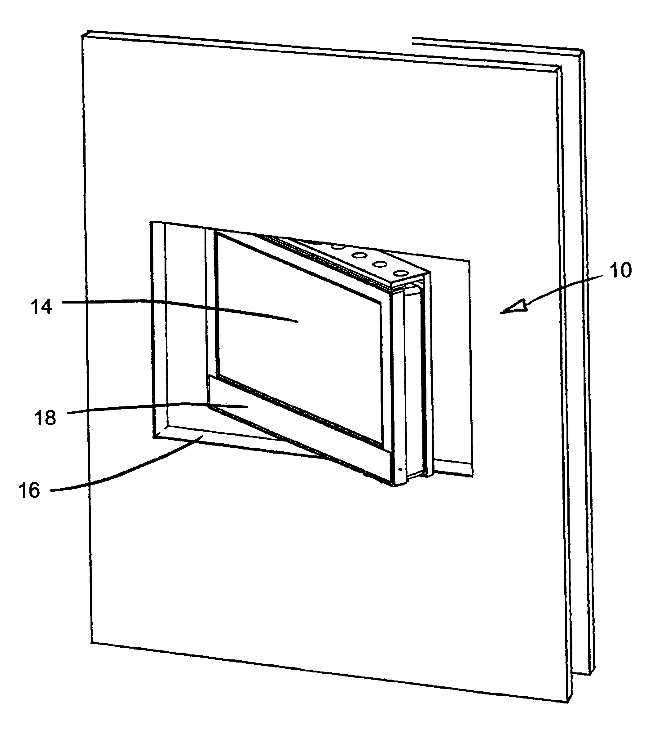
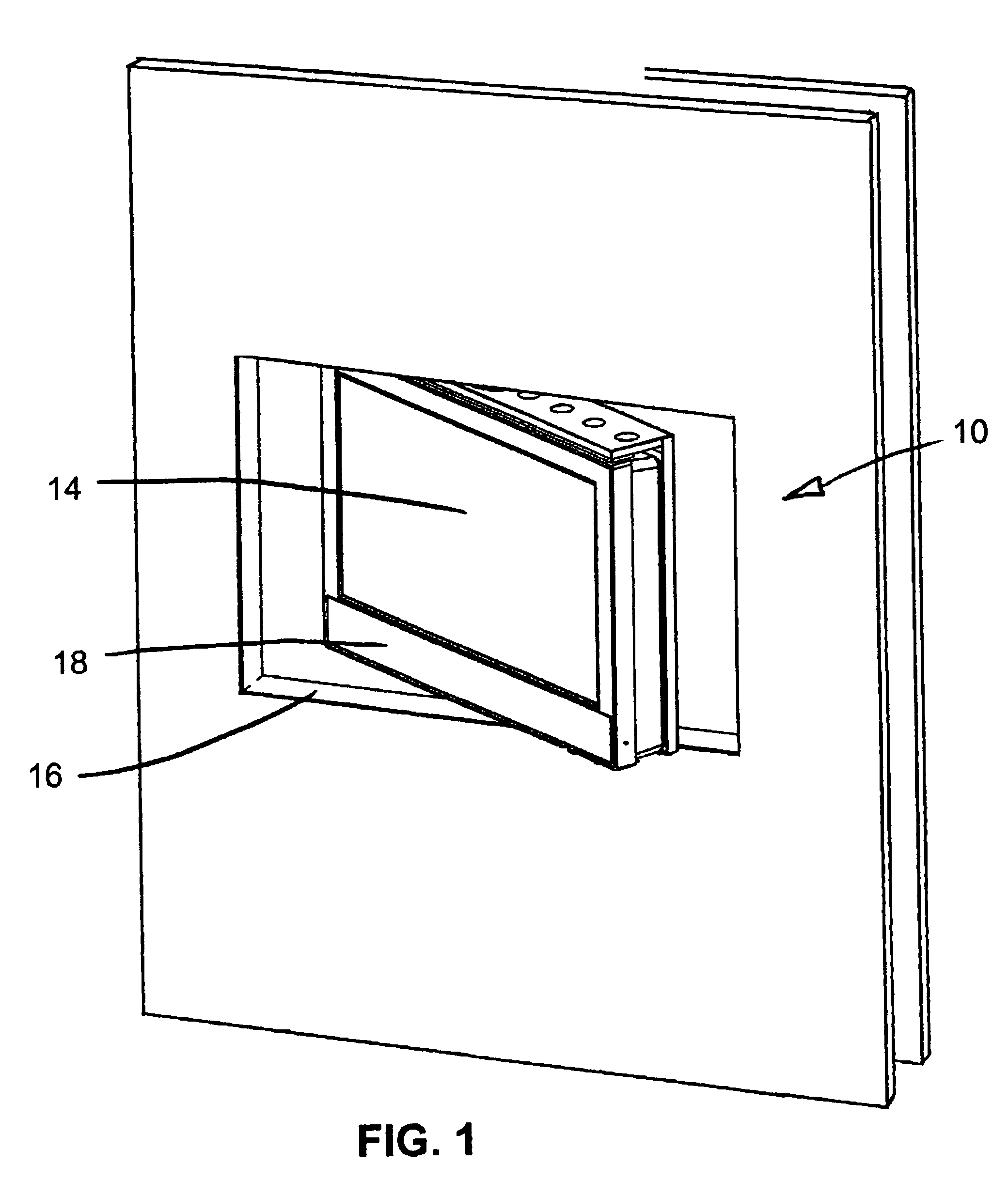
[0034]Referring to FIGS. 1 to 9, the mounted rotatable television unit of the present invention is shown generally at 10. Unit 10 is mounted into a wall 12 opening created in an interior wall between two rooms such that the user can watch the television 14 from either room by rotating the television unit 180 degrees. The television would have the same look facing either direction.

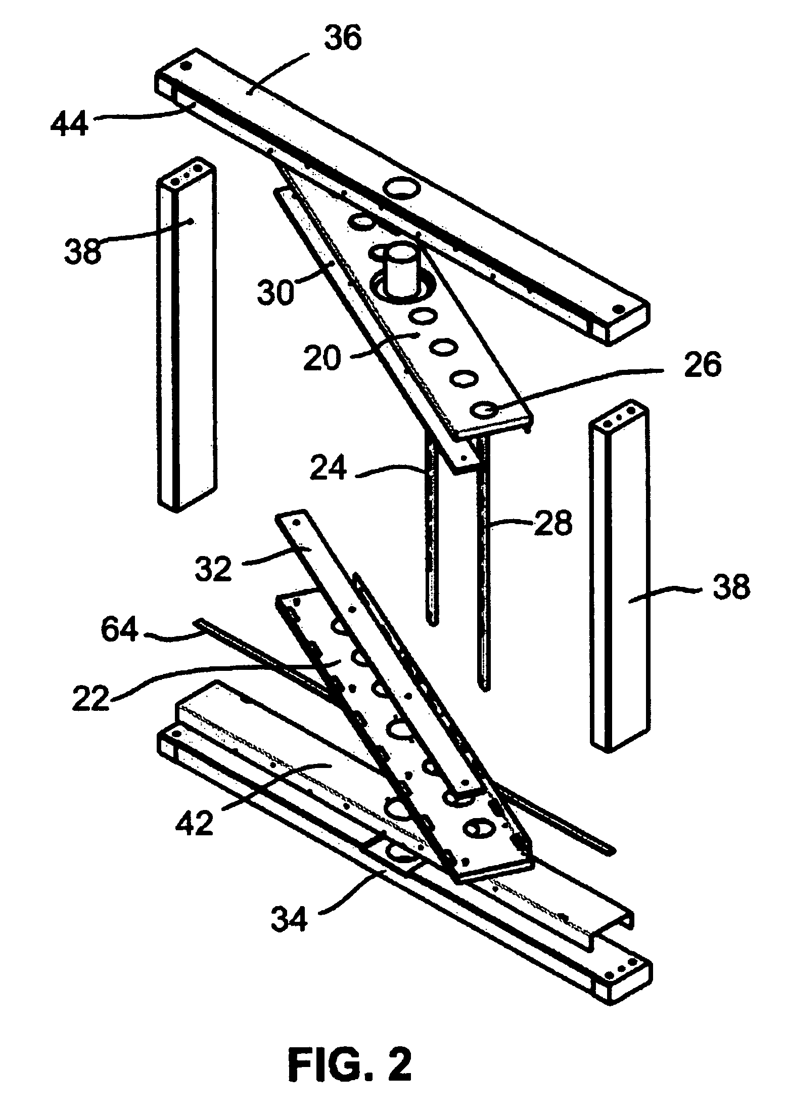
[0035]The mounted rotatable television unit 10 of the present invention includes an outer frame 16 and an inner frame 18. The inner frame 18 includes a top rotatable bracket 20, a bottom rotatable bracket 22 and a pair of rear mounting brackets 24. The top and bottom rotatable brackets 20, 22 each have a plurality of vent holes 26 formed therein. Rear mounting brackets 24 have a plurality of mounting apertures 28 formed therein. The mounting apertures 28 are positioned to be in registration with the standard mounting holes on a television 14. The spacing between the rear mounting brackets 24 is determined b...


PUM


Abstract

The present invention is a mounted rotatable television unit for installing a television in one of a wall and a cabinet wherein when installed therein the television is rotatable at least 180 degrees. The unit has an inner frame and an outer frame. The inner frame is adapted to receive a television. The outer frame is adapted to be installed in one of the wall and the cabinet and is rotatably attached to the inner frame whereby the inner frame may be pivoted such that the television is rotatable at least 180 degrees.

Description

CROSS REFERENCE TO RELATED PATENT APPLICATION[0001]This patent application relates to U.S. Provisional Patent Application Ser. No. 60 / 701,939 filed on Jul. 25, 2005 entitled WALL MOUNTED SWIVEL TELEVISION UNIT which is incorporated herein by reference in its entirety.FIELD OF THE INVENTION[0002]This invention relates to television units and in particular television units that are mounted in a wall and can be viewed from either side of the wall.BACKGROUND OF THE INVENTION[0003]Televisions seem almost ubiquitous; it seems that they are found in virtually all homes in North America. Further in some homes televisions are found in every room. While homes in some areas are getting smaller, televisions are getting larger. Accordingly the situation of the television in a home is both a space and a design issue.[0004]A number of devices have been suggested by which a television is attached to a wall, ceiling or table. Specifically there are a number of patents directed to devices for support...

Claims


Application Information

Patent Timeline
Patent Type & Authority Patents(United States)
IPC IPC(8): H04N5/645F16M13/00
CPCA47B81/065F16M11/08F16M11/18H04N5/64F16M2200/08
Inventor VERMEULEN, TIMOTHY JOHN
Owner VERMEULEN TIMOTHY JOHN
Learn More