
Seismic vibrator array and method for using

a vibrator array and seismic technology, applied in seismology, seismology, instruments, etc., can solve the problems of difficult control of the signal type and frequency content of the vibrator, the practical limit of using marine vibrators for such sophisticated signal schemes, and the low energy efficiency of the vibrator

Active Publication Date: 2012-01-10
PGS GEOPHYSICAL AS
View PDF57 Cites 40 Cited by
  • Summary
  • Abstract
  • Description
  • Claims
  • Application Information

AI Technical Summary

Benefits of technology

The patent describes a method for generating seismic energy for subsurface surveying. The method involves operating two seismic vibrators simultaneously, with driver signals that are uncorrelated with each other. This results in seismic signals that can be detected at multiple locations and used to gather information about the subsurface formations. The technical effect of this method is improved accuracy and resolution in seismic surveying.

Problems solved by technology

A practical limit to using marine vibrators for such sophisticated signal schemes is the structure of marine vibrators known in the art.
This means that the vibrator energy efficiency will be very low, principally at low frequencies but generally throughout the seismic frequency band, and such vibrators can be difficult to control with respect to signal type and frequency content.
Conventional marine seismic vibrators are also subject to strong harmonic distortion, which limits the use of more complex signals.

Method used


Image

  • Seismic vibrator array and method for using
  • Seismic vibrator array and method for using
  • Seismic vibrator array and method for using

Examples


Embodiment Construction

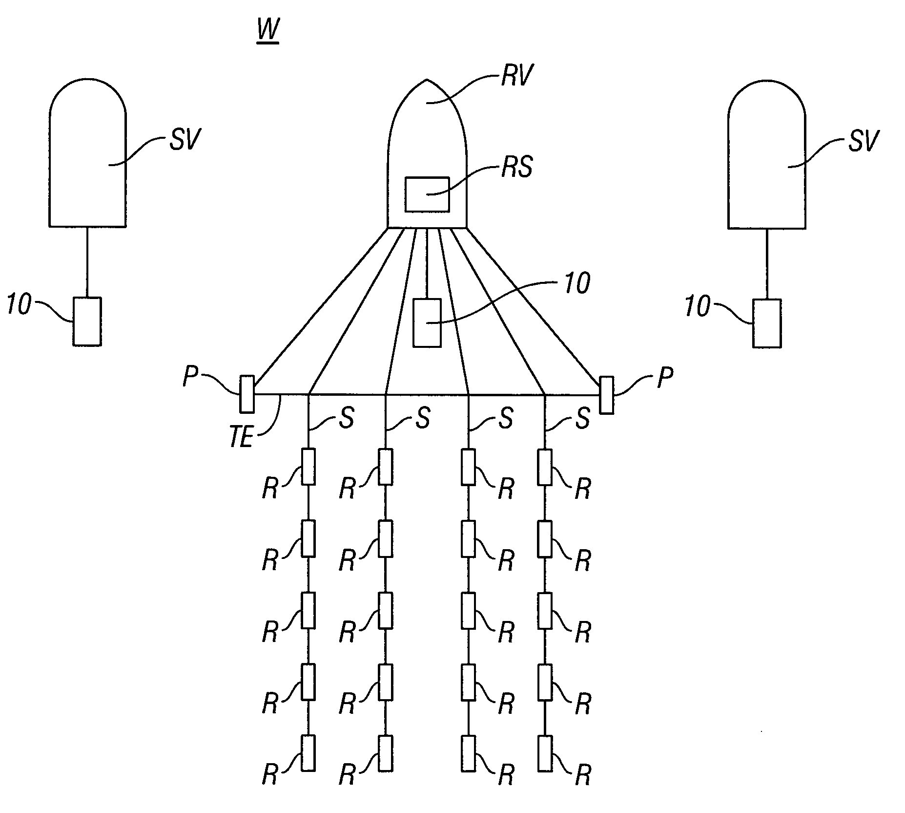
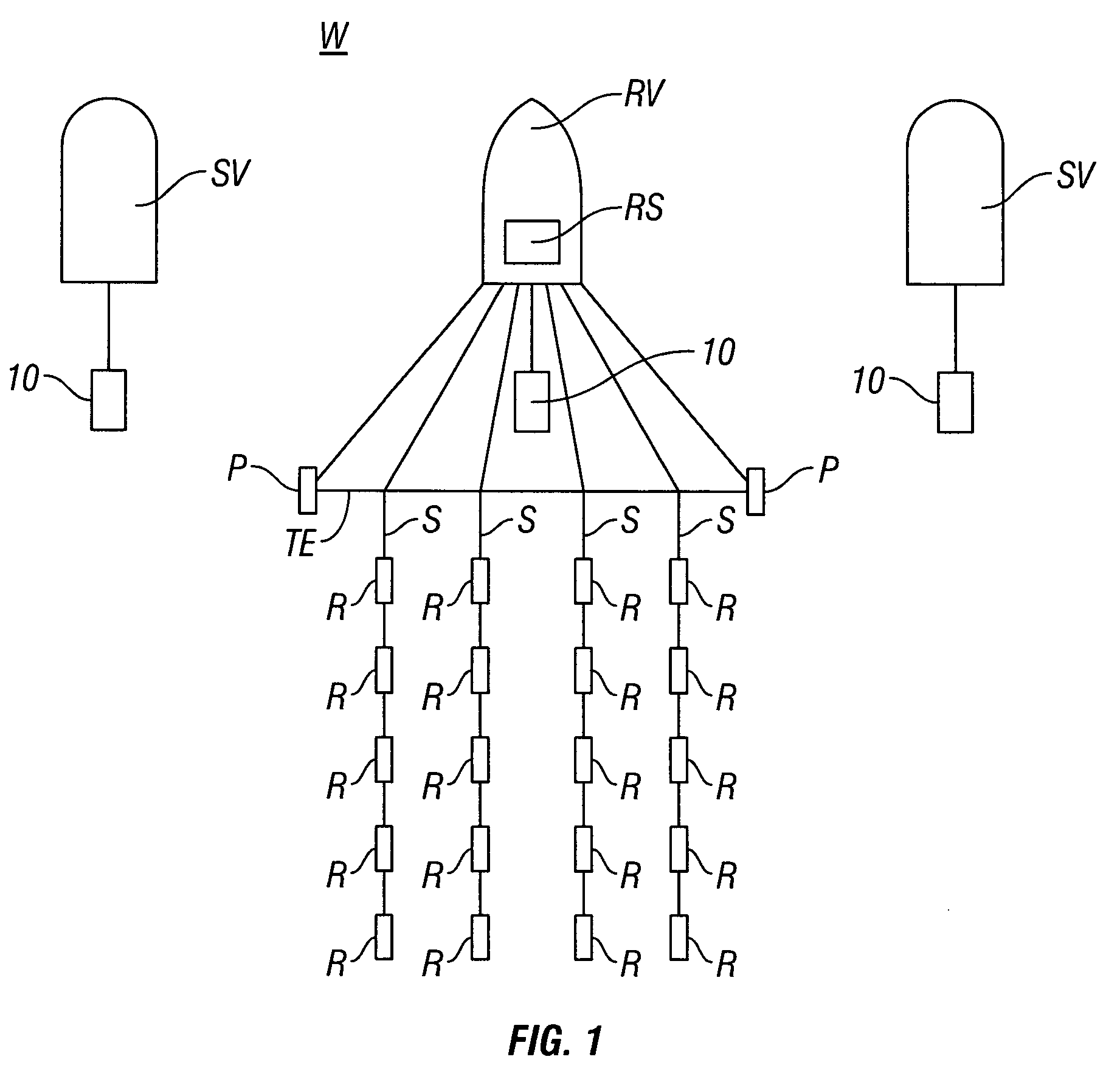
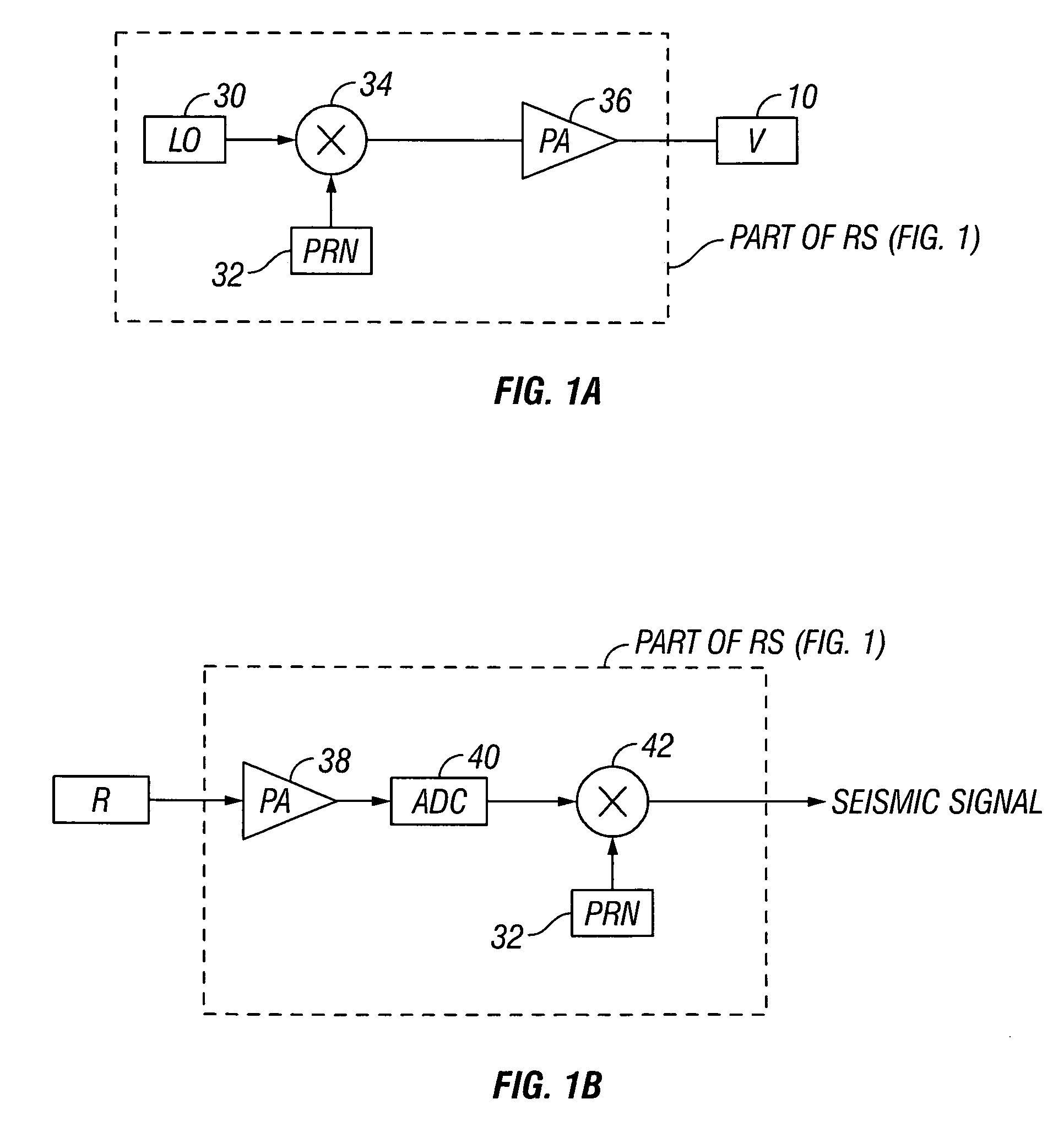
[0038]An example of marine seismic surveying using a plurality of marine vibrator seismic energy sources is shown schematically in FIG. 1. A seismic survey recording vessel RV is shown moving along the surface of a body of water W such as a lake or the ocean. The seismic survey recording vessel RV typically includes equipment, shown at RS and referred to for convenience as a “recording system” that at selected times actuates one or more seismic energy sources 10, determines geodetic position of the various components of the seismic acquisition system, and records signals detected by each of a plurality of seismic receivers R.

[0039]The seismic receivers R are typically deployed at spaced apart locations along one or more streamer cables S towed in a selected pattern in the water W by the recording vessel RV (and / or by another vessel). The pattern is maintained by certain towing equipment TE including devices called “paravanes” that provide lateral force to spread the components of th...


PUM


Abstract

A method for generating seismic energy for subsurface surveying includes operating a first seismic vibrator and operating at least a second seismic vibrator substantially contemporaneously with the operating the first seismic vibrator. A driver signal to each of the first and the at least a second seismic vibrators that are substantially uncorrelated with each other.

Description

CROSS-REFERENCE TO RELATED APPLICATIONS[0001]Not applicable.STATEMENT REGARDING FEDERALLY SPONSORED RESEARCH OR DEVELOPMENT[0002]Not applicable.BACKGROUND OF THE INVENTION[0003]1. Field of the Invention[0004]This invention relates generally to geophysical exploration and in particular to a vibratory seismic source useful in geophysical exploration. More particularly, the invention relates to methods for using vibrators for marine seismic acquisition.[0005]2. Background Art[0006]Seismic energy sources, including vibrators, are used in geophysical exploration on land and in water covered areas of the Earth. Acoustic energy generated by such sources travels downwardly into the Earth, is reflected from reflecting interfaces in the subsurface and is detected by seismic receivers, typically hydrophones or geophones, on or near the Earth's surface or water surface.[0007]In marine seismic surveying, a seismic energy source such as an air gun or an array of such air guns is towed near the su...

Claims


Application Information

Patent Timeline
Patent Type & Authority Patents(United States)
IPC IPC(8): G01V1/38
CPCG01V1/006G01V1/005
Inventor TENGHAMN, STIG RUNE LENNART
Owner PGS GEOPHYSICAL AS
Learn More