
Method, apparatus, and program for judging image recognition results, and computer readable medium having the program stored therein

a technology of image recognition and program, applied in the field of method, apparatus, and program for judging image recognition results, can solve the problems of placing a burden on users and a large workload on users, and achieve the effects of more accurate judgment of recognition results, easy understanding of recognition results, and predictable recognition accuracy with respect to each processing target imag

Active Publication Date: 2011-12-20
FUJIFILM CORP
View PDF24 Cites 9 Cited by
  • Summary
  • Abstract
  • Description
  • Claims
  • Application Information

AI Technical Summary

Benefits of technology

The present invention relates to an apparatus and method for recognizing and measuring predetermined structures in images. The apparatus includes an image recognition means that recognizes the predetermined structure in the image, a structure measuring means that measures the predetermined structure, and a recognition result judging means that determines whether the anatomical measurement value falls within a predetermined standard range. The method involves recognizing the predetermined structure in the image, measuring it, and determining if it falls within the standard range. The invention can be used in various fields such as medical diagnosis and sports equipment design. The technical effects of the invention include improved accuracy in recognizing and measuring predetermined structures in images and the ability to automatically correct recognition results.

Problems solved by technology

Generally, not all of image recognition results are correct, and it is necessary to check and correct errors of the recognition results, and manual checking and correction thereof places a burden on the part of users.
In particular, in the case of three-dimensional images obtained by CT, MRI, or the like, checking target images may amount to huge, so that manual checking and correction causes a large amount of workload on the users.

Method used


Image

  • Method, apparatus, and program for judging image recognition results, and computer readable medium having the program stored therein
  • Method, apparatus, and program for judging image recognition results, and computer readable medium having the program stored therein
  • Method, apparatus, and program for judging image recognition results, and computer readable medium having the program stored therein

Examples


embodiments 1 to 3

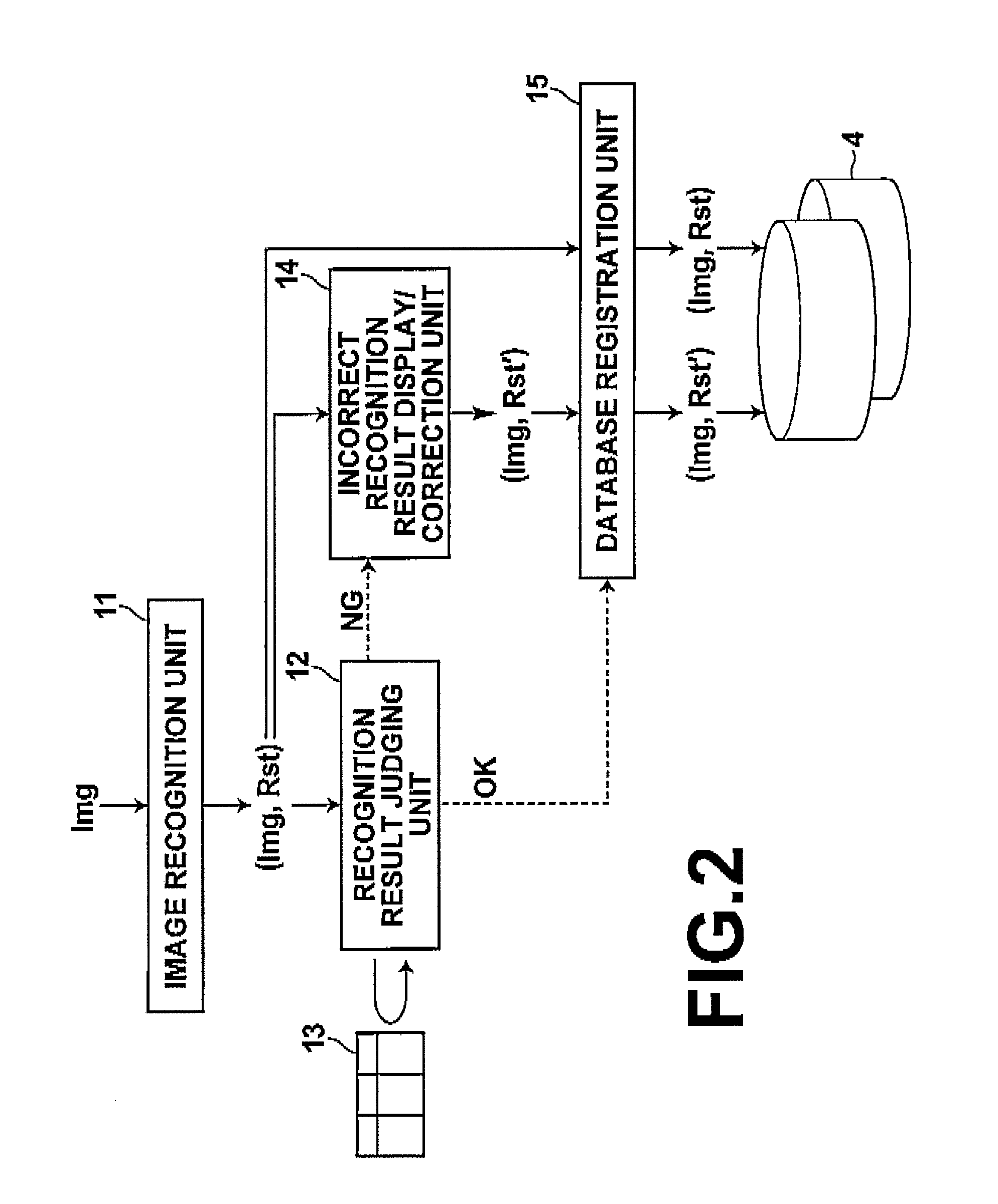
FIG. 4 is a block diagram of a structure recognition result correction apparatus that realizes structure recognition / correction processing according to a first embodiment of the present invention, schematically illustrating the configuration and data flow thereof. As illustrated, the apparatus includes a structure recognition unit 21 (corresponding to the image recognition unit 11 shown in FIG. 2), a recognition result judging unit 22 (corresponding to the recognition result judging unit 12 shown in FIG. 2), a standard structure length table 23 (corresponding to standard range table 13), a region correction unit 24 (corresponding to incorrect recognition result display / control unit shown in FIG. 2), and a database registration unit 31 (corresponding to the database registration unit 15). The structure recognition unit 21 recognizes a structure Pn of a body represented by each of tomographic images SLn (n=1, 2, - - - ), and the recognition result judging unit 22 obtains a length of e...

second embodiment

In the region recognition result correction apparatus according to the present invention, it is assumed that the length of each region follows a predetermined probability distribution, and a reliability level in the probability distribution is obtained, then a reliability range in the probability distribution is obtained based on the obtained reliability level, and judgment of recognition result is made with the reliability range as a predetermined length range.

FIG. 16 is a block diagram of the recognition result judging unit 22 according to the present embodiment, illustrating the processing thereof in detail. As illustrated, the recognition result judging unit 22 additionally includes a reliability level obtaining unit 75 in comparison with the configuration shown in FIG. 9. Further, processing of the standard region length obtaining unit 73 and construction of the standard region length table 23 are different in comparison with the first embodiment in the following way.

The reliab...

third embodiment

In the region recognition result correction apparatus according to the present invention, attribute information representing an attribute of a subject is obtained, then a length range is predetermined according to the obtained attribute information, and judgment of recognition results is made using the predetermined length range.

FIG. 18 is a block diagram of the recognition result judging unit 22 according to the present embodiment, schematically illustrating the detailed processing thereof. As illustrated, the processing of the accessory information analysis unit 71 and the standard region length obtaining unit 73 differs from that of those shown in FIG. 9, in addition to the construction of the standard region length table 23 in the following way.

The accessory information analysis unit 71 obtains body height information Bh as well as analyzing inputted tomographic images SLn and obtaining a slice position PSn of each of the tomographic images.

FIGS. 19A, 19B, and 19C illustrate an ...


PUM


Abstract

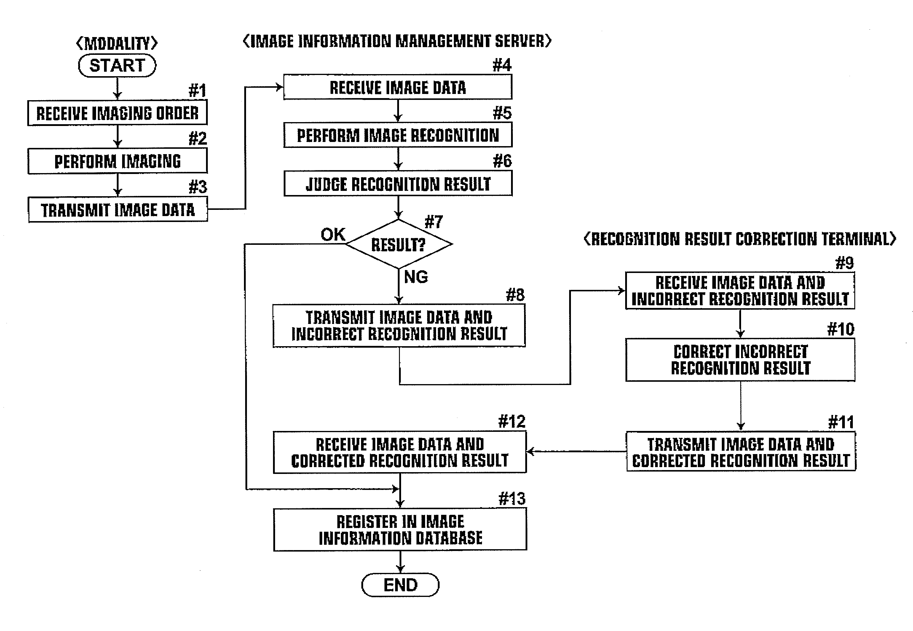
To obtain more accurate image recognition results while alleviating the burden on the user to check the image recognition results. An image recognition unit recognizes a predetermined structure in an image representing a subject, then a recognition result judging unit measures the predetermined structure on the image recognized by the image recognition unit to obtain a predetermined anatomical measurement value of the predetermined structure, automatically judges whether or not the anatomical measurement value falls within a predetermined standard range, and, if it is outside of the range, judges the image recognition result to be incorrect.

Description

BACKGROUND OF THE INVENTION1. Field of the InventionThe present invention relates to an apparatus and method for judging whether or not recognition results of image recognition processing performed on medical images are correct. The invention also relates to a computer readable recording medium having a program stored therein for causing a computer to perform the method.2. Description of the Related ArtA variety of technologies for recognizing various structures in medical images are proposed. For example, a technology for recognizing structures represented by tomographic images obtained by imaging a subject with an imaging modality, such as CT or MRI, is known. More specifically, a method in which input images are classified into categories based on medical image management information and image size, then a plurality of candidate template images are selected from a storage storing template images with respect to each category to be recognized using the classification result of the...

Claims


Application Information

Patent Timeline
Patent Type & Authority Patents(United States)
IPC IPC(8): G06K9/00G06K9/64
CPCG06K9/6201G06K2209/051G06V2201/031G06F18/22
Inventor MORIYA, YOSHIYUKI
Owner FUJIFILM CORP
Learn More