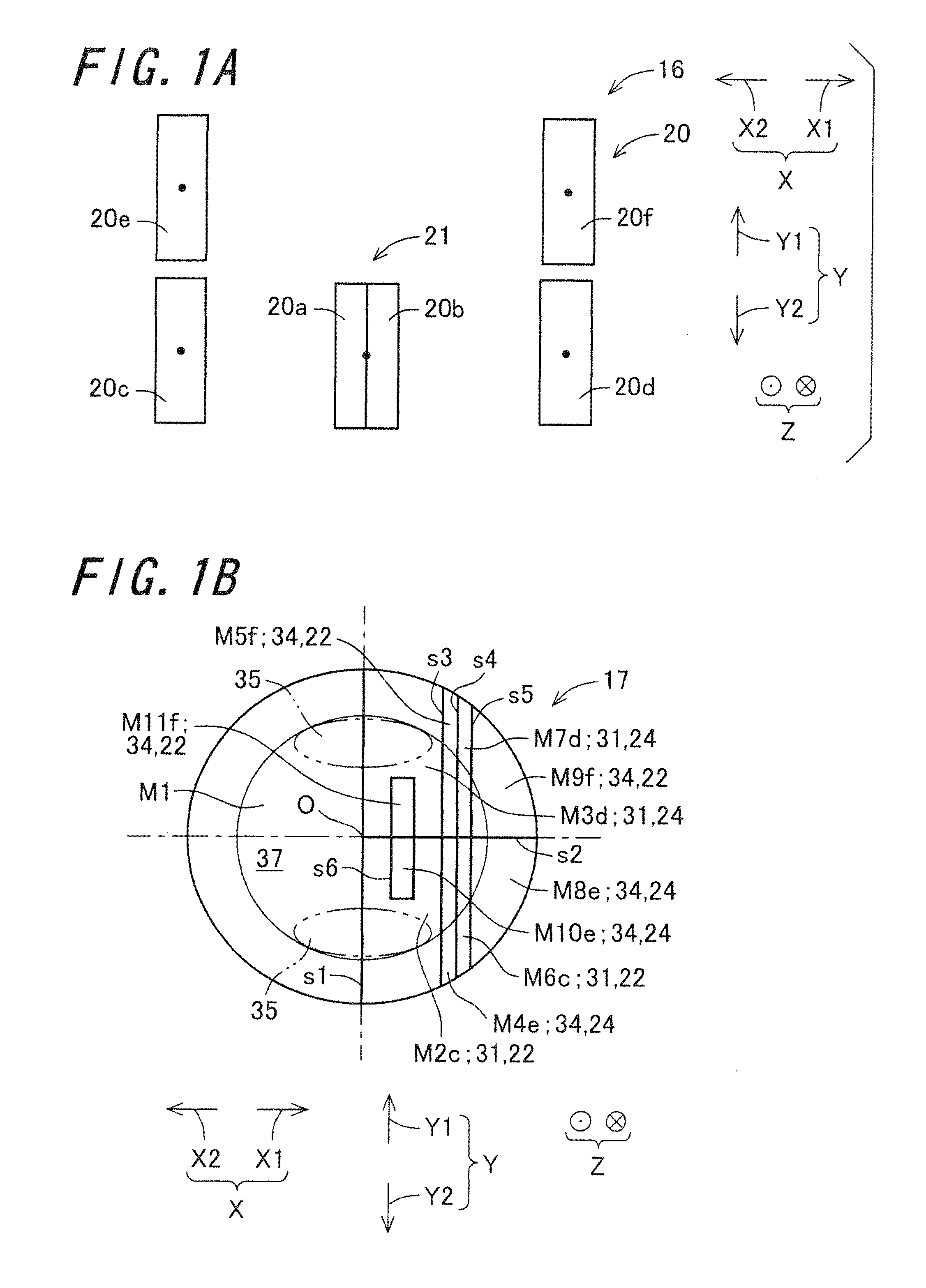
[0034]According to the example embodiment, in the diffraction element, a plurality of the forward regions and the reverse regions are arranged alternately in a tangential direction which corresponds to, out of the directions parallel to the diffraction element, the direction of a line tangent to the track at a position where light condensed by the objective lens enters the surface of the optical recording medium.
[0033]This makes it possible to decrease the possibility that the foreign-matter shade affects only one of the first diffraction region and the second diffraction region on the diffraction element, and thereby decrease the possibility that the foreign-matter shade affects only one of the push-pull light-receiving region and the offset light-receiving region of the light-receiving element. In this way, with the influence of the quantity of light entering the simple area taken away from the quantity of light entering the bright-dark contrast area on the diffraction element, at the time of push-pull signal calculation, it is possible to eliminate the influence of simple diffraction light entering the bright-dark contrast area, as well as to achieve cancellation of the influences of the foreign-matter shade. In consequence, a higher degree of accuracy in the push-pull signal is achievable compared to the related-art technology.
[0036]According to the example embodiment, a shape of the second diffraction region is so determined that a quantity of light entering the second diffraction region is proportional to an amount of deviation of the objective lens from the track.
[0037]In this case, in contrast to a case where the quantity of light entering the second diffraction region bears a non-linear relationship with the amount of deviation of the objective lens from the track, the formula used for push-pull signal calculation can be simplified, wherefore computation cost required for push-pull signal calculation can be reduced correspondingly. This makes it possible to obtain a radial error in a short period of time and with high accuracy, as well as to render the time taken for radial error correction as short as possible. Accordingly, the objective lens can be driven under control with higher accuracy.
[0038]According to the example embodiment, the diffraction element includes regions of which each constitutes at least part of either of the forward region and the reverse region, and at least part of the regions is rectangularly formed so that the tangential direction becomes its lengthwise direction.
[0039]This helps increase the possibility that, in the diffraction element, the foreign-matter shade extends over the forward region and the reverse region adjacent to each other in a radial direction. When the foreign-matter shade extends over the forward region and the reverse region adjacent to each other, in terms of the push-pull signal, the influence of the foreign-matter shade on the forward region and that of the foreign-matter shade on the reverse region can be synchronized with each other. Accordingly, push-pull signal fluctuation resulting from the on-the-diffraction-element movement of the foreign-matter shade projected on the diffraction element can be suppressed. This makes it possible to achieve mutual cancellation of the influence of the foreign-matter shade on the forward region and that on the reverse region.
[0040]According to the example embodiment, in the diffraction element, a plurality of the forward regions and the reverse regions are arranged alternately in a radial direction which is parallel to the diffraction element and perpendicular to the tangential direction.
[0041]By doing so, in contrast to the case of arranging a plurality of the forward regions and the reverse regions alternately in the tangential direction of the diffraction element, it is possible to easily insure timewise synchronization between the foreign-matter shade's projective entrance to the forward region and its projective entrance to the reverse region. Meanwhile, alternate arrangement of the forward regions and the reverse regions in the tangential direction affords the advantage to decrease the possibility that the foreign-matter shade is projected lopsidedly on one side, i.e. one of the forward region and the reverse region. By contrast, with the alternate arrangement of the forward regions and the reverse regions in the radial direction, the influence of the foreign-matter shade, which is projected so as to extend over the adjacent forward region and reverse region, on the forward region and that on the reverse region can be perfectly synchronized with each other. In consequence, the foreign-matter influence on the forward region and that on the reverse region cancel each other out.
[0042]According to the example embodiment, the diffraction regions constitute a first array and a second array. In the first array, a plurality of the forward regions and the reverse regions are arranged alternately in the tangential direction. In the second array, a plurality of the forward regions and the reverse regions are arranged alternately in the radial direction.
[0043]This makes it possible to form the first array in that part of the diffraction element in which a phase difference arises between the waveform of the output signal corresponding to the forward region and the waveform of the output signal corresponding to the reverse region, as well as to form the second array in that part of the diffraction element in which the waveform of the output signal corresponding to the forward region and the waveform of the output signal corresponding to the reverse region are in the same phase. Accordingly, in contrast to the case of arranging a plurality of the forward regions and the reverse regions alternately in only one specific direction in the diffraction element, in terms of the influence of the foreign-matter shade on the push-pull signal, the output signal corresponding to the forward region and the output signal corresponding to the reverse region can be synchronized with each other with a higher degree of accuracy. This helps stabilize the push-pull signal even further.
[0044]According to the example embodiment, the light-receiving element has an independent light-receiving region, and an output signal from the independent light-receiving region is not used for push-pull signal calculation. The diffraction element includes an independent diffraction region and the second diffraction region. The independent diffraction region is formed centrally of the diffraction element in the radial direction, and diffracts the incident light so that it can be directed to the independent light-receiving region. The second diffraction region is formed outwardly from the independent diffraction region in the radial direction.
[0045]By virtue of the independent diffraction region, the increase and decrease of the quantity of light entering the radial midportion of the diffraction element is independent of that of the push-pull signal. The second diffraction region is located radially outwardly from the independent diffraction region, the edges of which extends in the tangential and radial directions. Thereby, the quantity of light entering the radial midportion of the diffraction element that is relatively large in the intensity of incident light per unit area becomes irrelevant to the light quantity used for push-pull signal calculation. This leads to easiness in determining the shape of the second diffraction region in such a manner that the quantity of incident light is proportional to the amount of deviation of the objective lens from the track.
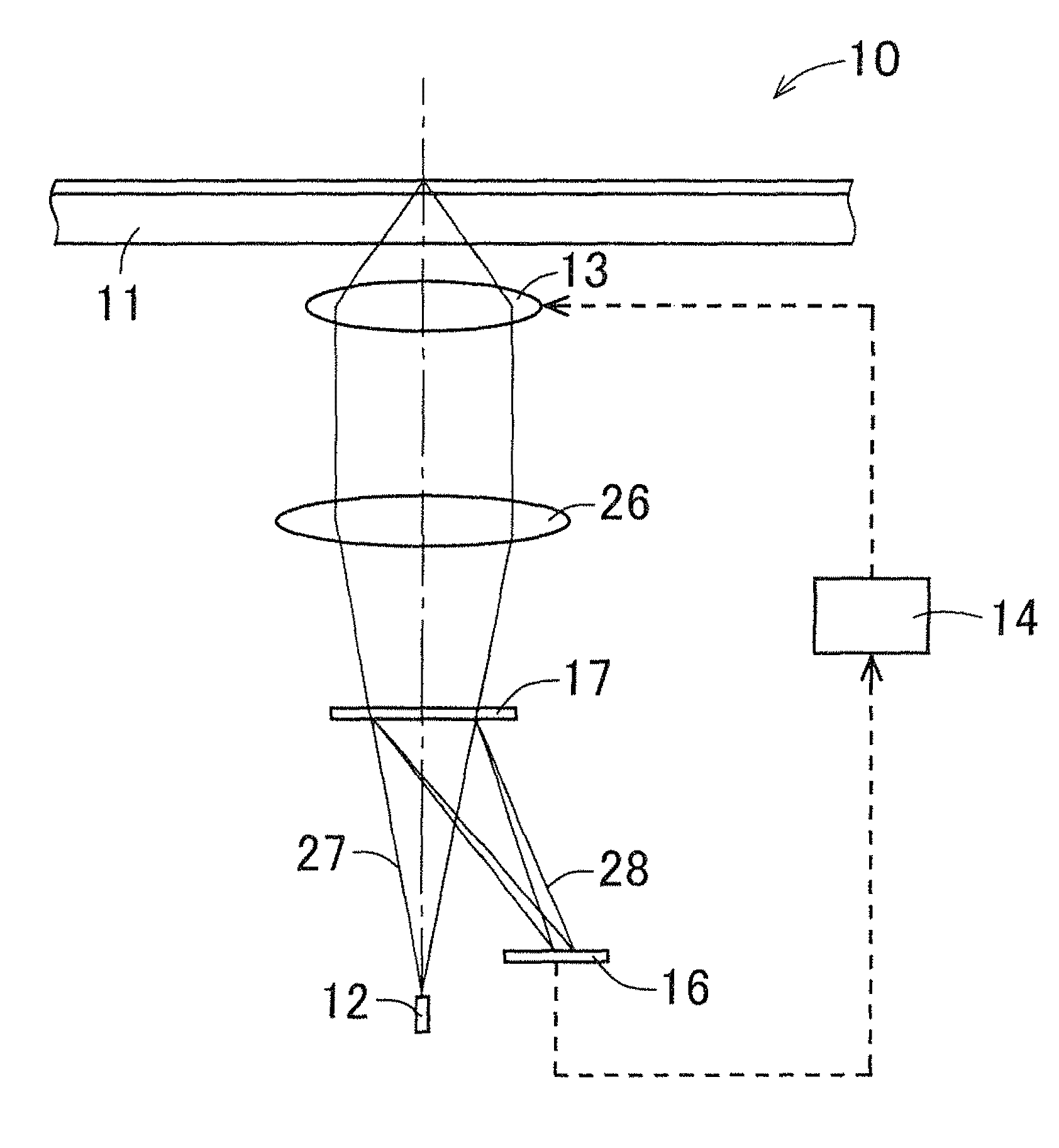
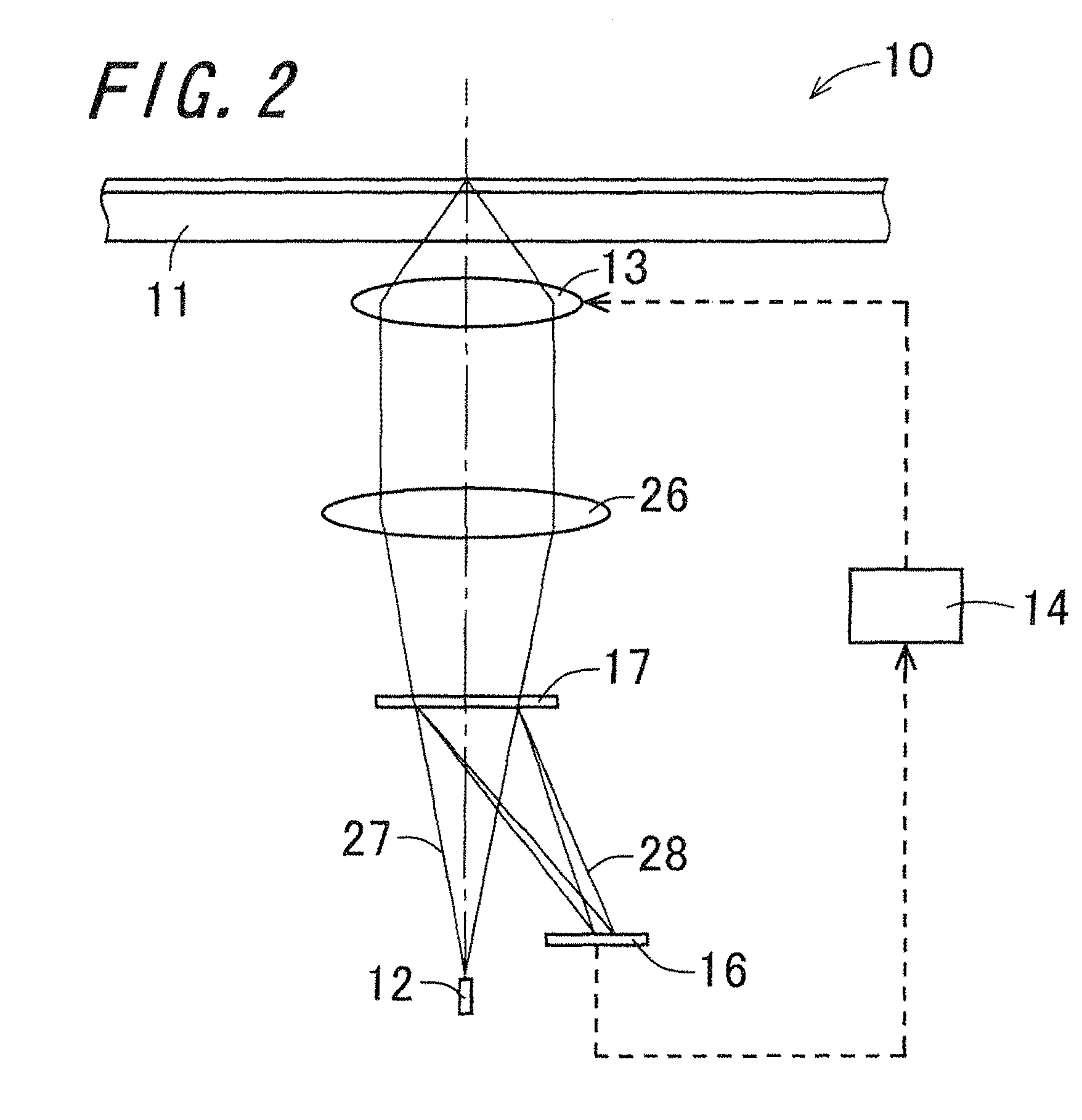
[0049]Thereby, focus error detection and radial error detection can be achieved by the common diffraction element and light-receiving element. Therefore, as compared with the case of disposing one of the diffraction element and the light-receiving element in a separate unit for focus error detection and radial error detection, the optical pickup apparatus can be made more compact.
[0050]According to the example embodiment, in response to an output signal from the focus error detecting region, the control-driving section produces a focus error signal by a knife edge method.
[0053]In this case, as compared with the case of effecting focus error detection by the differential push pull method for instance, the light-receiving region used for focus error detection can be smaller in size, wherefore the optical pickup apparatus can be made more compact.
[0055]Accordingly, when mounted in combination with other components, the optical pickup apparatus can be handled with the light source, the diffraction element, and the light-receiving element secured in their relative positions. This leads to easiness in mounting operation.
[0055]Accordingly, when mounted in combination with other components, the optical pickup apparatus can be handled with the light source, the diffraction element, and the light-receiving element secured in their relative positions. This leads to easiness in mounting operation.


