
Implantable intervertebral fusion device

a technology of intervertebral fusion and fusion device, which is applied in the field of implantable intervertebral fusion device, can solve the problems of further instability of the spine, increased adverse spinal conditions, and displaced or damaged spinal discs, and achieve the effect of restoring disc space height and spine curvatur

Inactive Publication Date: 2011-10-25
OSPREY BIOMEDICAL
View PDF347 Cites 21 Cited by
  • Summary
  • Abstract
  • Description
  • Claims
  • Application Information

AI Technical Summary

Benefits of technology

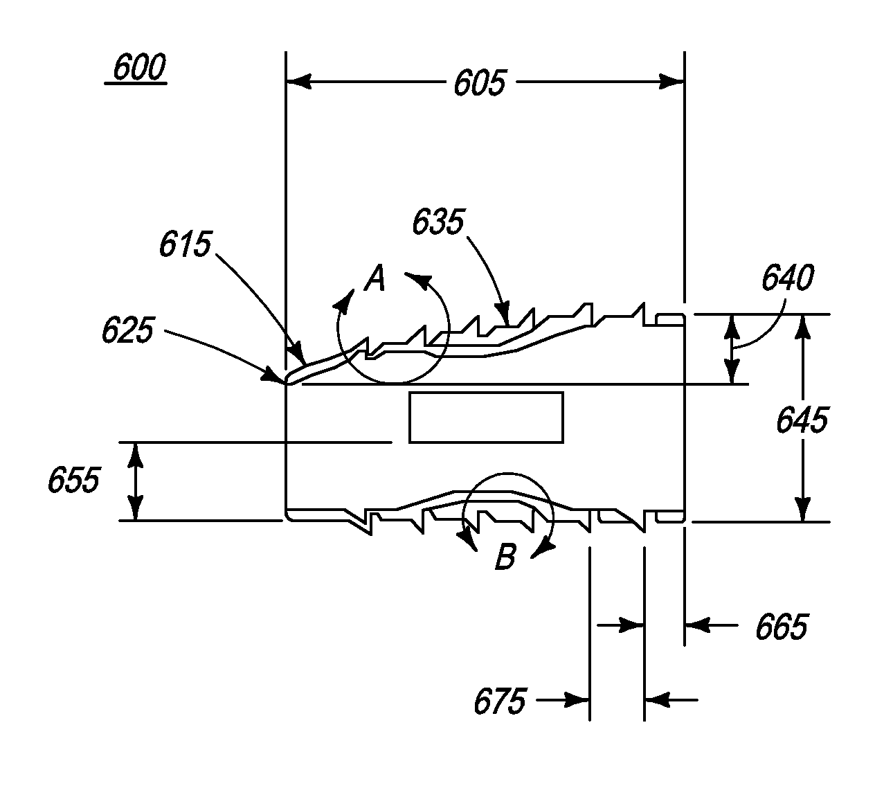
[0025]Optionally, the bone body has a wedge-shaped profile to adapt anatomically to a curvature of a plurality of lumbar vertebras endplates. Optionally, the bone body has a wedge-shaped profile to help restore disc space height and spine curvature. Optionally, an angle of the wedge shaped profile lies between 7° to 9°.

Problems solved by technology

As populations age, it is anticipated that there will be an increase in adverse spinal conditions which are characteristic of aging.
Spinal discs may be displaced or damaged as a result of disease, trauma, aging or injury to the spine.
The removal of the damaged or unhealthy disc without reconstruction would allow the disc space to collapse, resulting in further instability of the spine, abnormal joint mechanics, premature development of arthritis or nerve damage, in addition to severe pain.
The osteogenic fusion material consisted of cortical-cancellous bone which was not strong enough to support the weight of the spinal column at the instrumented level.
With this technique, once the fusion occurs, the hardware maintaining the stability of the spine becomes superfluous.
There are other several disadvantages associated with the use of the abovementioned metal implants.
Solid body metal implants do not effectively enable bone in-growth which may lead to the eventual failure of the implant.
Surface porosity in such solid implants does not correct this problem because it will not allow sufficient in-growth to provide a solid bone mass strong enough to withstand the loads of the spine.
The abovementioned intervertebral fusion device has substantial disadvantages, however.
The metallic supporting frame of the prior art fusion cages is not osteoconductive and therefore does not form a strong mechanical attachment to a patient's bone tissue.
This can lead to graft necrosis, poor fusion and poor stability.
Moreover, many of these devices are difficult to machine and therefore expensive.
Furthermore, the fusion cages may stress shield the bone graft, increasing the time required for fusion to occur.
In addition, the use of bone graft materials in the prior art metal cage fusion devices presents several disadvantages.
Autografts, bone material surgically removed from the patient, are undesirable because the donor site may not yield a sufficient quantity of graft material.
The additional surgery to extract the autograft also increases the risk of infection, persistent pain, and may reduce structural integrity at the donor site.
One problem with the implant devices of the type mentioned above is that they tend not to maintain the normal curvature of the spine.
Loss of lordosis and proper intervertebral spacing may result in an increased risk of degeneration to other intervertebral discs located adjacent to the fusion level due to the alteration of the overall mechanics of the spine.
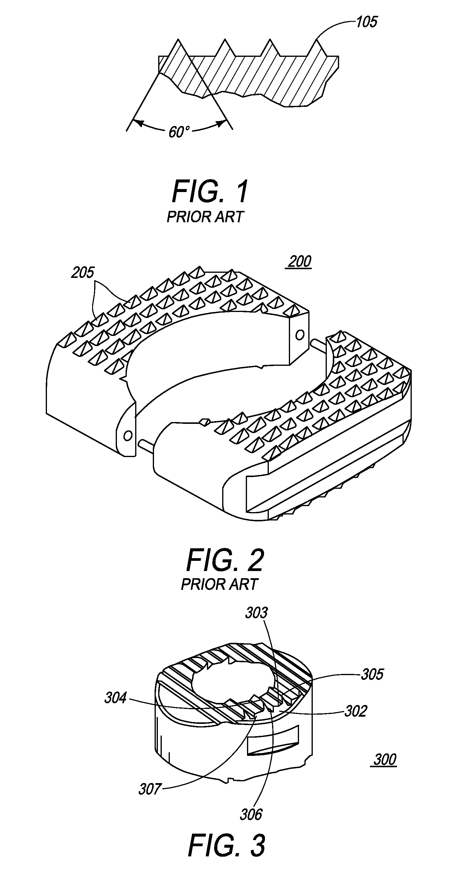
A further problem with the abovementioned implant is that the cylindrical geometry of the engaging element tends to provide a small area of contact between the engaging element and the vertebrae.
However, the implants are not sufficiently effective at preventing expulsion of the implant.

Method used


Image

  • Implantable intervertebral fusion device
  • Implantable intervertebral fusion device
  • Implantable intervertebral fusion device

Examples


Embodiment Construction

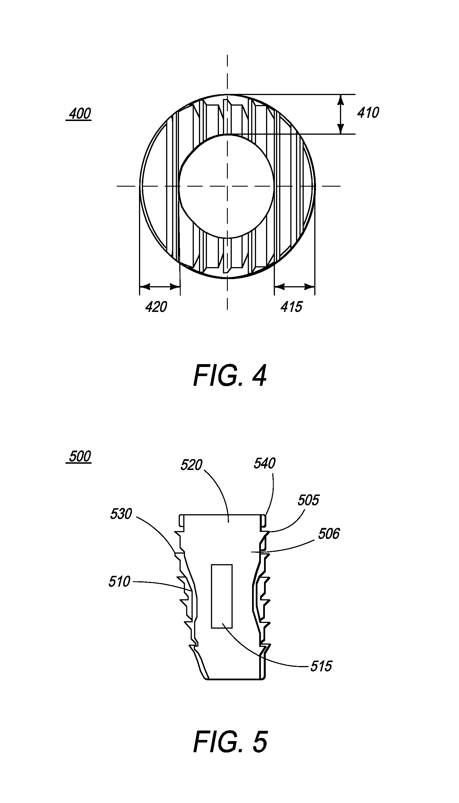
[0046]The present invention relates to an implantable intervertebral fusion device for use when surgical fusion of vertebral bodies is indicated. The implant is comprised of an allogenic cortical bone conforming in size and shape with the end plates of the adjacent vertebrae and has a wedge-shaped profile with a plurality of footings and grooves located on the top and bottom surfaces.

[0047]The top and bottom surface of the implant has a macro-texture and a micro-texture. The macro-structure is formed by a series of continuous footings and grooves that cross the implant from side to side. The relative placement of each footing and groove defines a surface upon which an osteoconductive and / or osteoinductive micro-structure may be applied. The top surface of the implantable device is a convex surface with its apex at the back of the implant and the bottom surface is flat planar surface or curved surface to match the topography of the end plate.

[0048]The lateral corners of the implantab...


PUM


Abstract

The present invention relates to an implantable intervertebral fusion device for use when surgical fusion of vertebral bodies is indicated. The implant is comprised of bone conforming in size and shape with the end plates of the adjacent vertebrae and has a wedge-shaped profile with a plurality of footings and grooves located on the top and bottom surfaces.

Description

FIELD OF THE INVENTION[0001]The present invention relates generally to an implantable intervertebral fusion device and, more specifically, to allograft bone devices with an anatomical shape that effectively conforms to, and adheres to, the endplates of the adjacent vertebras. The present invention is also directed to methods of using a series of continuous footings and grooves for strong mechanical attachment to the patient bone tissue.BACKGROUND[0002]The vertebral column is a bio-mechanical arrangement composed largely of ligaments, muscles, vertebrae, and intervertebral discs. The bio-mechanical functions of the spine include: (1) support of the body, which involves the transfer of the weight and the bending movements of the head, trunk and arms to the pelvis and legs; (2) complex physiological motion between these parts; and (3) protection of the spinal cord and nerve roots.[0003]As populations age, it is anticipated that there will be an increase in adverse spinal conditions whi...

Claims


Application Information

Patent Timeline
Patent Type & Authority Patents(United States)
IPC IPC(8): A61F2/44
CPCA61F2/30771A61F2/4465A61F2/28A61F2/4611A61F2/4644A61F2002/2835A61F2310/00359A61F2002/302A61F2002/3082A61F2002/30904A61F2230/0004A61F2230/0065A61F2002/30112
Inventor GUYER, RICHARD D.ZIGLER, JACK E.LEE, RANDALL F.CLOKIE, CAMERON
Owner OSPREY BIOMEDICAL
Learn More