
Elongated probe

a probe and elongation technology, applied in the field of elongated probes, can solve the problems of reducing increasing the differential pressure capability, and reducing so as to reduce the loss of seals, reduce the damage during use, and increase the differential pressure capability

Active Publication Date: 2011-09-13
SCHLUMBERGER TECH CORP
View PDF25 Cites 13 Cited by
  • Summary
  • Abstract
  • Description
  • Claims
  • Application Information

AI Technical Summary

Benefits of technology

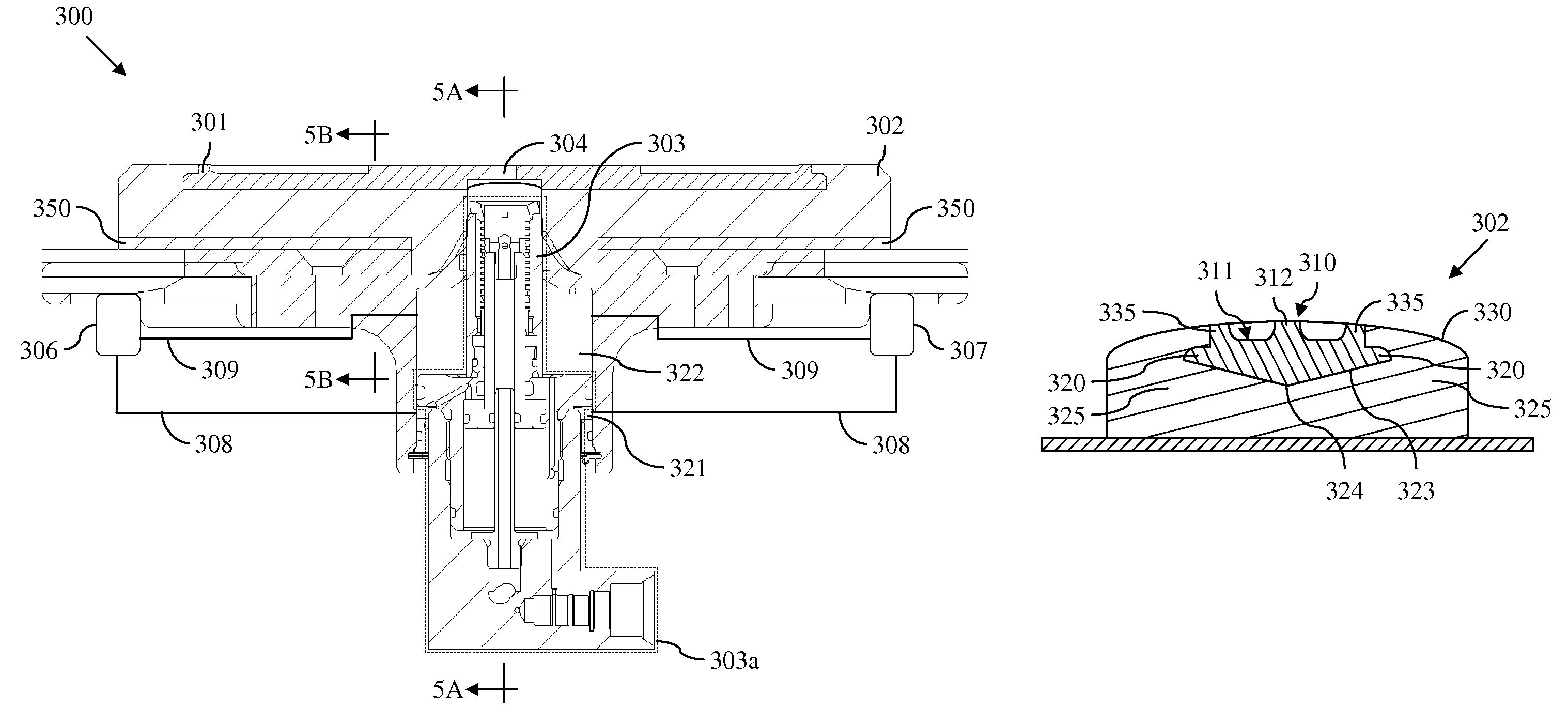
The present patent introduces a concept of embedding a reinforcement plate into the elastomeric structure of a packer for a formation testing probe assembly. This embedded plate can provide a surface against which a hydraulically actuated probe barrel can press, ensuring the tool is firmly locked in place and maintains near constant hydraulic system sealed volume as measurements are completed. The embedded plate can also provide a support structure that constrains the inward movement of the elastomer material of the packer, reducing damage during use and increasing differential pressure capability. The design can lead to reduced lost seal incidents and improved efficiency of the formation testing probe assembly.

Problems solved by technology

The proposed design may lead to reduced damage during use, increased differential pressure capability, and / or reduced lost seal incidents.

Method used


Image

  • Elongated probe
  • Elongated probe
  • Elongated probe

Examples


Embodiment Construction

It is to be understood that the following disclosure provides many different embodiments, or examples, for implementing different features of various embodiments. Specific examples of components and arrangements are described below to simplify the present disclosure. These are, of course, merely examples and are not intended to be limiting. In addition, the present disclosure may repeat reference numerals and / or letters in the various examples. This repetition is for the purpose of simplicity and clarity and does not in itself dictate a relationship between the various embodiments and / or configurations discussed. Moreover, the formation of a first feature over or on a second feature in the description that follows may include embodiments in which the first and second features are formed in direct contact, and may also include embodiments in which additional features may be formed interposing the first and second features, such that the first and second features may not be in direct ...


PUM


Abstract

A formation testing probe assembly comprising an elongated packer having a surface configured to be urged by the probe assembly towards a wall of a wellbore extending through the formation. The formation testing probe assembly further comprises a plate embedded in the elongated packer and including a central structural portion extending along a centerline of a substantial length of the plate, wherein the central structural portion is substantially thicker than remaining portions of the plate.

Description

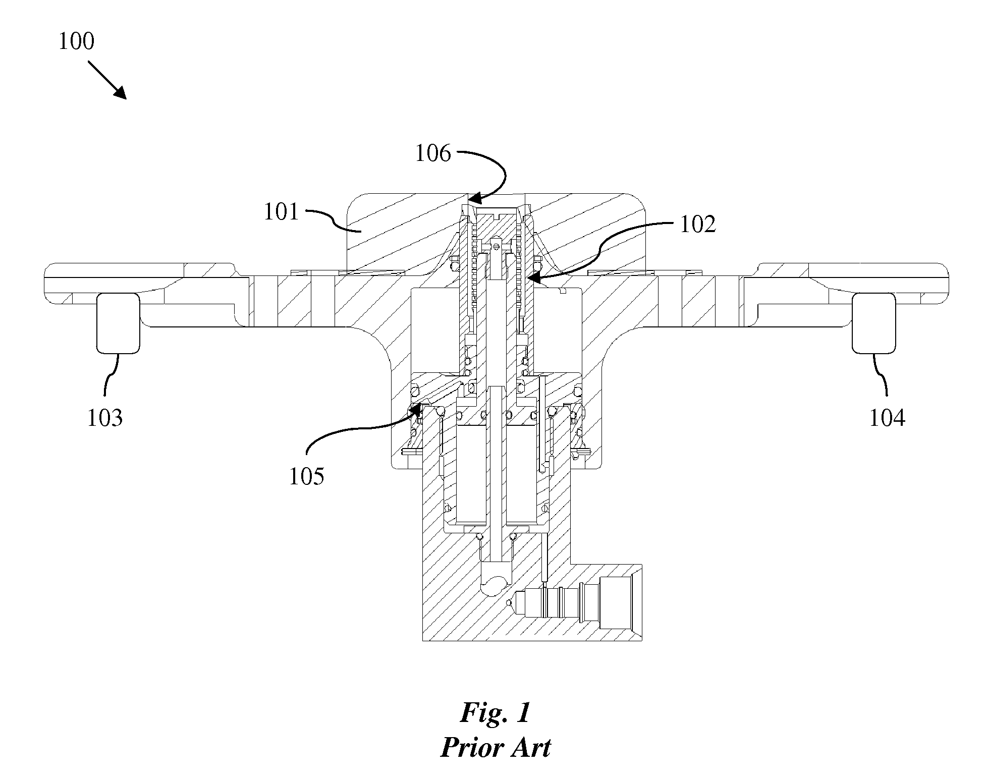
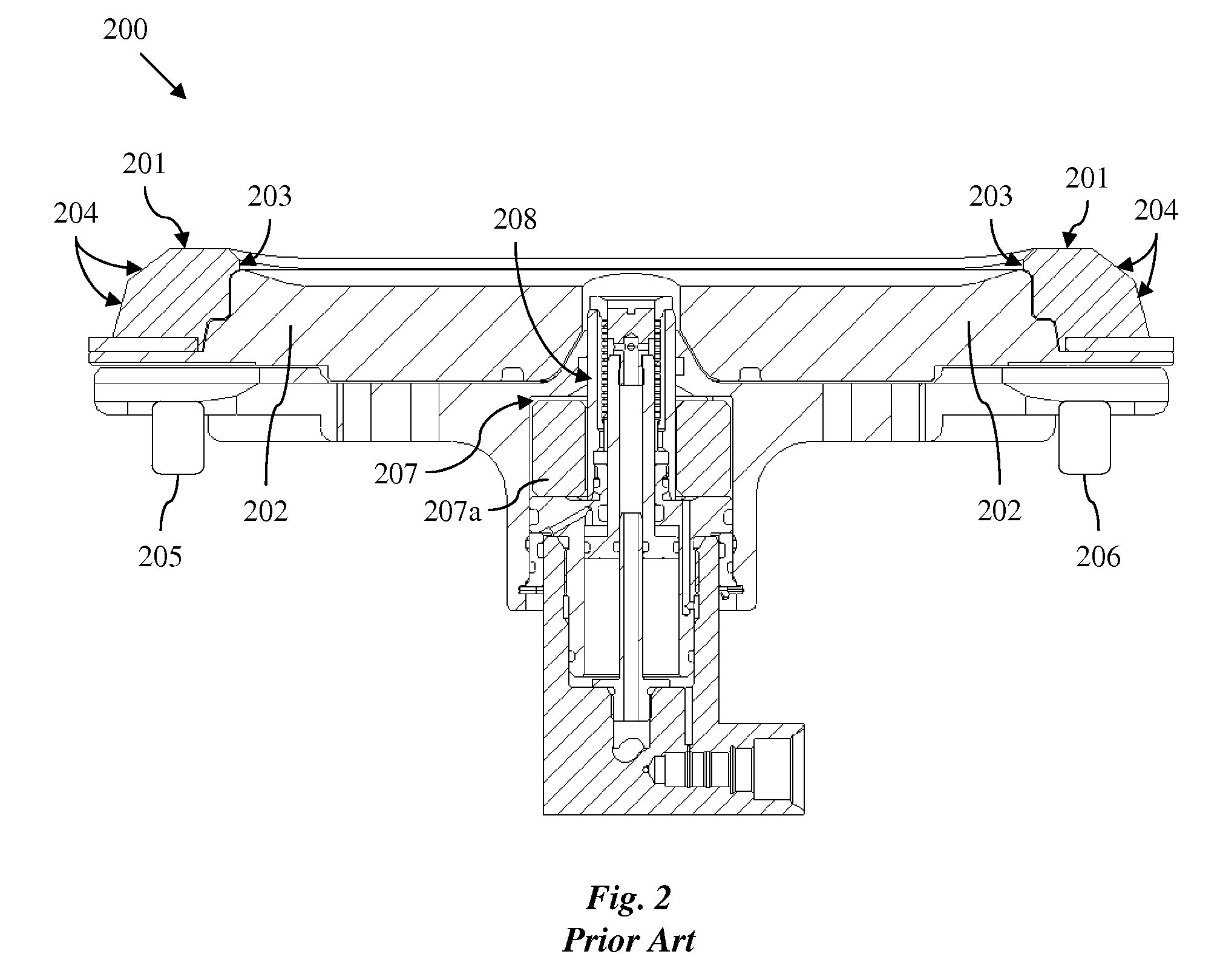
BACKGROUNDFIG. 1 is a cross-section of a known formation testing / sampling probe assembly 100 viewed in a plane containing the wellbore axis. The assembly 100 includes a packer 101 configured to be pressed against a formation of interest via hydraulically actuated pistons schematically shown as 103 and 104. Deformation of the packer 101 around an extendable probe barrel 102 and against the formation creates a seal that isolates the formation fluids and pressure from the wellbore environment. The probe barrel 102 extends forward, due to high pressure hydraulic oil entering chamber 105 at the same time pistons 103 and 104 are actuated to apply an extension force. The area of investigation by the probe assembly 100 is limited to the area that is in direct contact with the extendable probe barrel 102, usually called the orifice. This area is limited by the diameter of the probe barrel 102, which is about the same dimension as the diameter of the hole 106 in the packer 101 through which t...

Claims


Application Information

Patent Timeline
Patent Type & Authority Patents(United States)
IPC IPC(8): E21B49/10
CPCE21B49/10
Inventor KERR, BRADLEYDUSSAN, V., ELIZABETH B.CHURCH, NATHAN
Owner SCHLUMBERGER TECH CORP
Learn More