
Detachable footrest for a vehicle

a footrest and vehicle technology, applied in the field of footrests, can solve the problems of affecting the safety of drivers or passengers, affecting the safety of passengers, and often having an urge to have their legs removed,

Active Publication Date: 2011-07-19
HARVEY MATTHEW C
View PDF10 Cites 9 Cited by
  • Summary
  • Abstract
  • Description
  • Claims
  • Application Information

AI Technical Summary

Benefits of technology

[0008]In another aspect, the present invention is directed to a footrest vehicle combination. The combination includes a vehicle having a first hinge mount and a second hinge mount for affixing a door to a side of the vehicle. The combination also includes a detachable footrest. The footrest includes a footrest having a surface area sized and shaped to accommodate a foot of a user and a support arm attached to a support structure. The foot rest also includes a first downward projection projecting from the support structure. The first downward projection is sized and shaped to fit wi

Problems solved by technology

However, there are some disadvantages to removing the door.
Second, drivers and passengers, with doors removed, often have an urge to have their limbs outside of the vehicle cab.
However, there typically is no safe place to position the driver's or passenger's leg outside the vehicle cab.
However, these existing foot pegs fail to provide a sufficient planar surface area to allow a stable resting platform for the user's foot.
Furthermore, none of the existing pegs are attached to the vehicle at more than one point.
Thus, the existing pegs are subject to structural failure because of a lack of redundant attachment points.
Furthermore, none of the existing foot pegs provide a stabilizer for stabilizing the foot peg against the vehicle and prevent undesirable movement of the foot peg.
In addition, these existing pegs require tedious attachment means, such as nuts and bolts, and are not easily removed or attached to the vehicle.

Method used


Image

  • Detachable footrest for a vehicle
  • Detachable footrest for a vehicle
  • Detachable footrest for a vehicle

Examples


Embodiment Construction

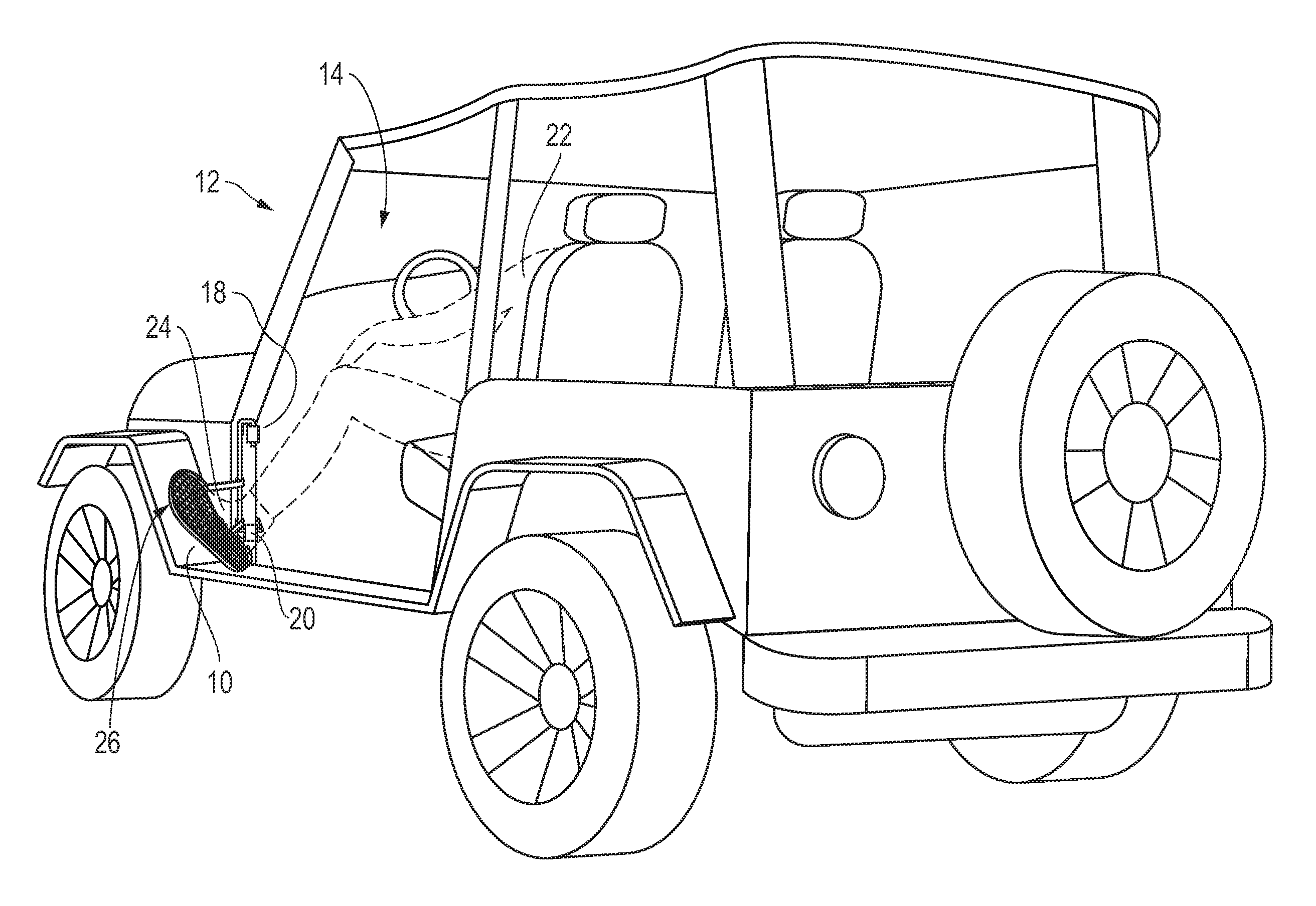
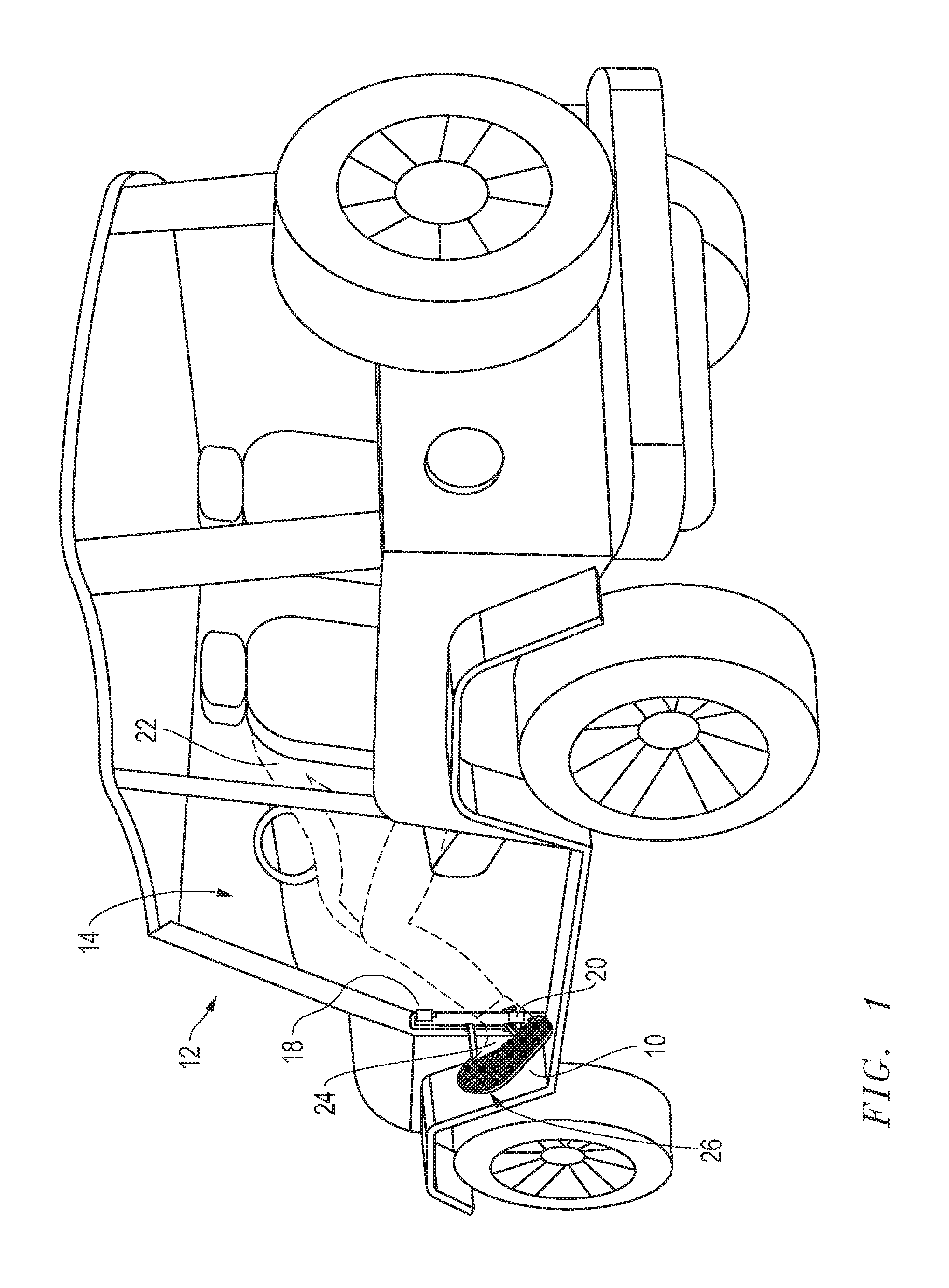
[0014]The present invention is a footrest which is easily attached and removed from a side portion of a vehicle. FIG. 1 is a rear perspective view of a left footrest 10 attached to a vehicle 12 in the preferred embodiment of the present invention. The vehicle includes an opening 14 where a side door (not shown) is normally situated. Typically, the door is attached at upper hinge mount 18 and lower hinge mount 20. In the preferred embodiment of the present invention, the footrest 10 is attached at the upper and lower mounts 18 and 20. When driving, a driver 22 may rest a foot 24 upon a planar surface 26 of the footrest.

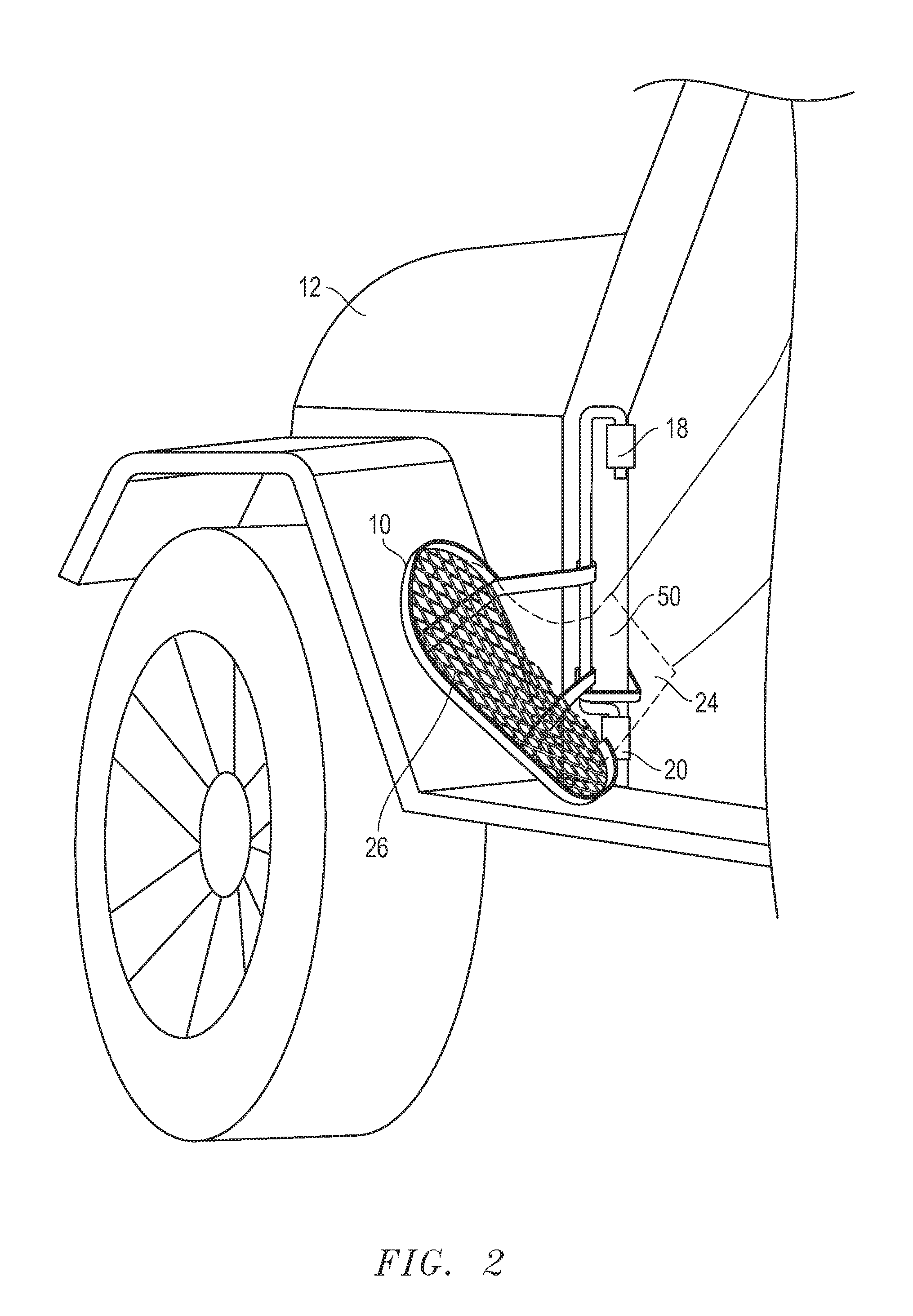
[0015]FIG. 2 is an enlarged side perspective view of the footrest 10 attached to the vehicle of FIG. 1. The upper hinge mount 18 and lower hinge mount 20 are typically cylindrical hinge structures having a bore running within the center of each mount. The door is normally affixed by support rods positioned within bores of each mount, thereby allowing the door to swing ...


PUM


Abstract

A detachable footrest for use on a vehicle. The footrest has a surface area sized and shaped to accommodate a foot of a user and at least one support arm attached to a support structure. The footrest also includes two downward projections projecting from the support structure. The downward projections are sized and shaped to fit within hinge mounts of a removed door of the vehicle. The projections are slid into the hinge mounts of the removed door of the vehicle, thereby providing a surface area outside of the vehicle for resting the foot of the user. The footrest may also include a stabilizer projecting from the support structure and fastened to a mounting post located in an interior of the vehicle.

Description

BACKGROUND OF THE INVENTION[0001]1. Field of the Invention[0002]This invention relates to accessories for vehicles. Specifically, and not by way of limitation, the present invention relates to a footrest for attachment to a side portion of a vehicle.[0003]2. Description of the Related Art[0004]Off-road vehicles are quite popular. These vehicles enable a driver to experience driving in its most basic and rustic form where paved roads are not always utilized. Furthermore, these vehicles oftentimes include detachable doors and roofs to enable the driver and any passengers to enjoy the outside environment. The driver is able to enjoy the open air while traveling, whether off-road or on the road. However, there are some disadvantages to removing the door. First, a side mirror is typically attached to the door, so when the door is removed, the mirror is also removed. Second, drivers and passengers, with doors removed, often have an urge to have their limbs outside of the vehicle cab. For ...

Claims


Application Information

Patent Timeline
IPC IPC(8): B60N3/06B62D25/20B62J25/00G05G1/60
CPCB60N2/24B60N3/06B62J29/00G05G1/60B62J25/00Y10T74/20918
Inventor HARVEY, MATTHEW C.
Owner HARVEY MATTHEW C
Learn More