Injector for viscous materials
a technology of viscous materials and injectors, which is applied in the field of ophthalmic surgery, can solve the problems of difficult to accurately and precisely control the amount of injection, and manual production of sufficient force with a syring
- Summary
- Abstract
- Description
- Claims
- Application Information
AI Technical Summary
Problems solved by technology
Method used
Image
Examples
example 1
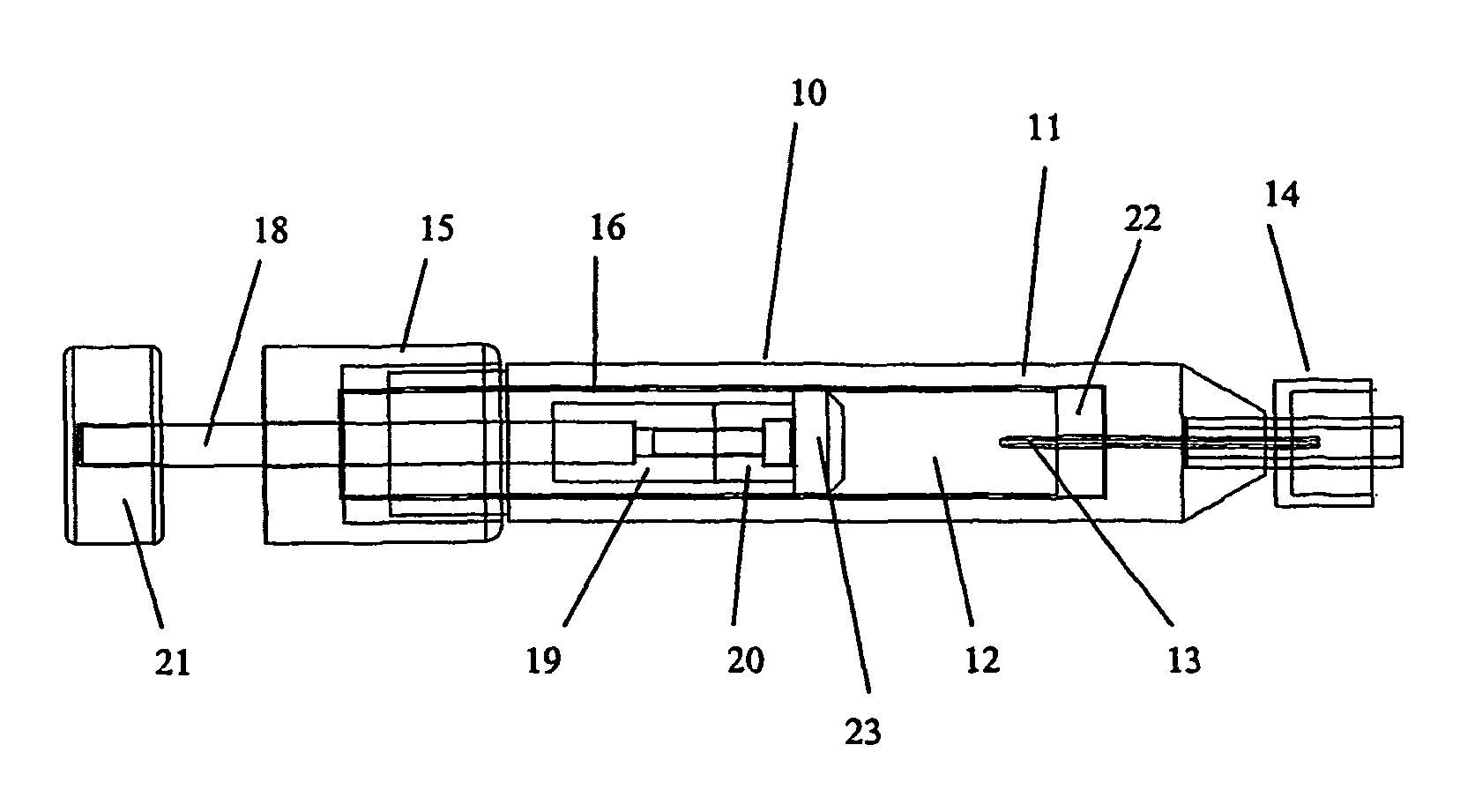
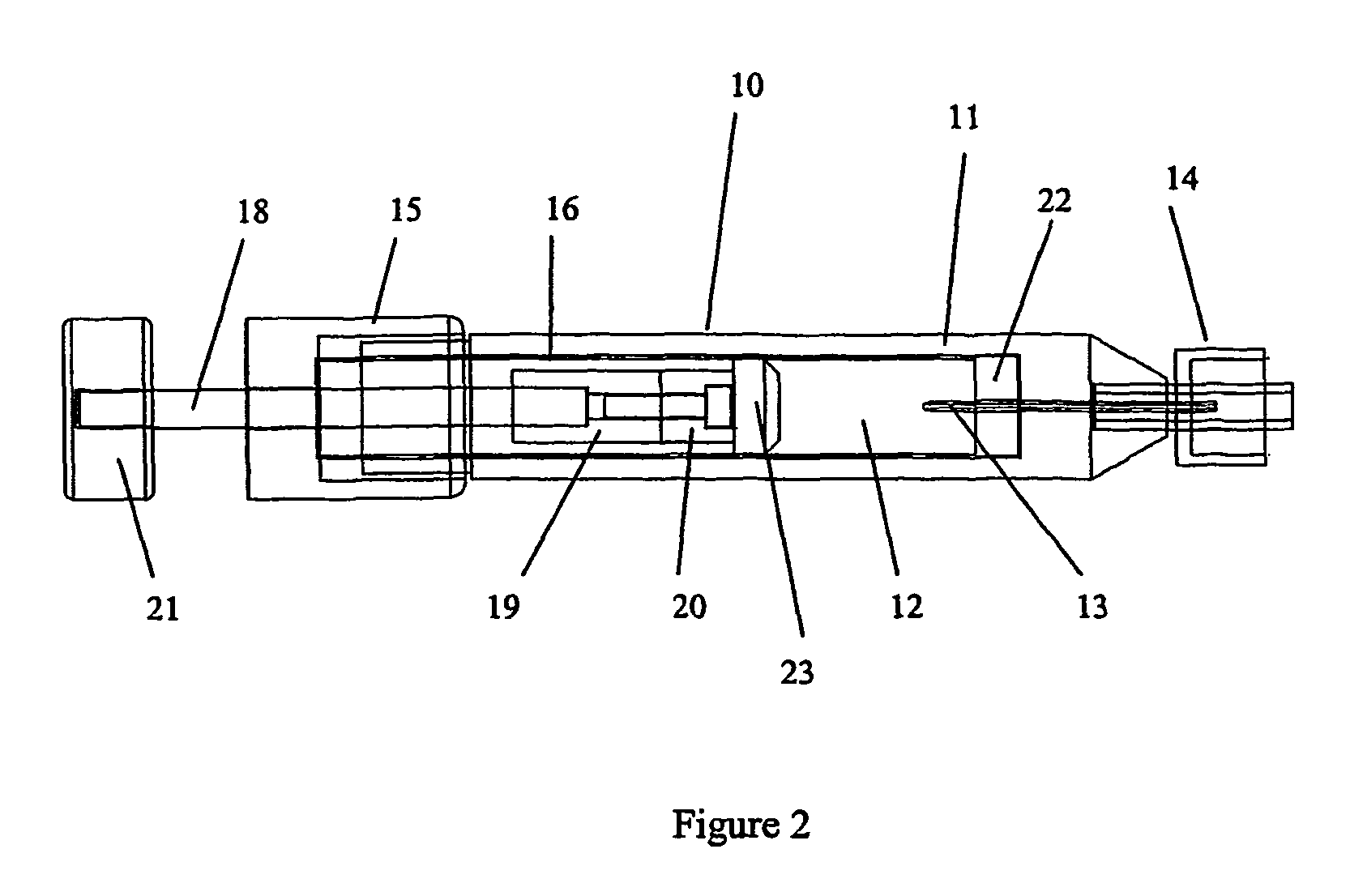
[0025]An injector was fabricated from a syringe body machined from polycarbonate, designed to receive a prefilled cartridge of viscoelastic material. At its distal end, a sharpened 22 gauge needle was bonded into a small axial through-hole in the syringe body. Concentric with the needle was a counterbore to accept a male luer fitting. The sharpened proximal end of the needle projected into the bore of the syringe in order to puncture the rubber septum of the cartridge when it was loaded into the syringe body. At its proximal end, the syringe body was externally threaded to mate to a cap and plunger assembly. The cap assembly consisted of an internally threaded (½-13 UNC) machined polycarbonate cap with a small threaded (5-40 UNC) hole through its center in which a threaded stainless steel rod was located. Attached to the distal end of the threaded rod was a polycarbonate plunger that had a low friction acetyl thrust bushing fastened to its face. A knurled thumbwheel was attached to ...
example 2
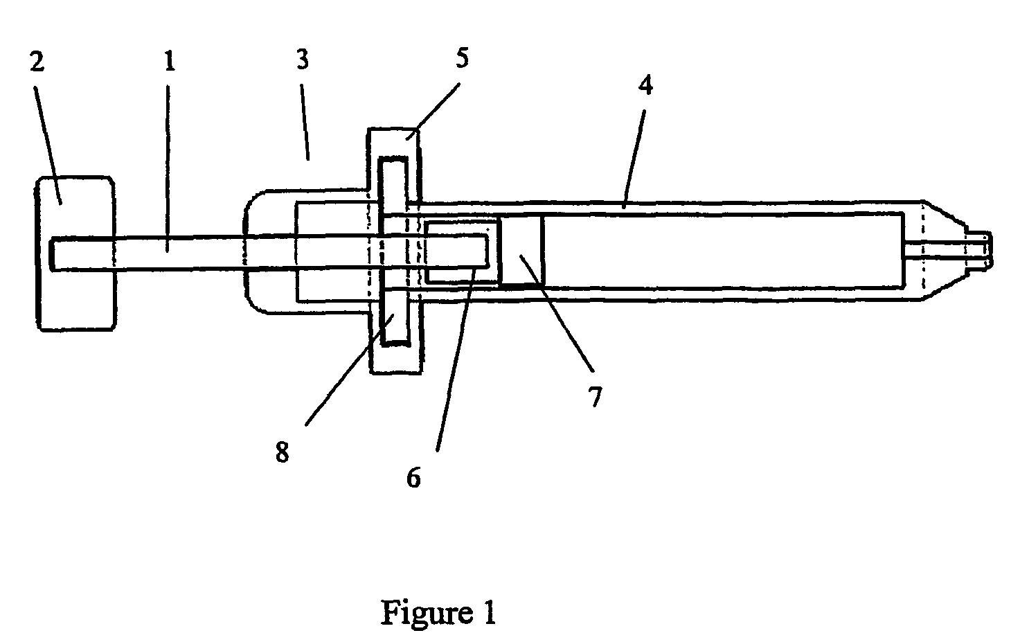
[0029]An injector was fabricated with a screw driven syringe plunger designed to receive a conventional syringe body. The device consisted of a cap portion which had a slot for insertion of the syringe flange, a feed screw for advancement of the plunger, and a thumbwheel for turning the feed screw. In preparation for use, the screw feed was retracted into its proximal most position. The flange on the syringe was then inserted into the slot in the cap, and the syringe bore was aligned with the axis of the cap. The screw was then advanced into the syringe bore until the plunger contacted the stopper in the syringe. Continuing to advance the screw resulted in viscoelastic material being ejected from the syringe body through the needle and luer fitting.
example 3
[0030]The injector of Example 1 was tested for delivery of three surgical viscoelastic materials, Healon, Healon GV, and Healon 5 (Advanced Medical Optics Inc.) with corresponding viscosities at zero shear of 300,000 mPas, 3,000,000 mPas and 7,000,000 mPas. Each viscoelastic material was delivered at ¼, ½, and 1 turn of the screw mechanism of the injector. The resulting material delivered was placed in a tared weigh boat and weighed on an analytical balance (Mettler AG285). The results are shown below in Table 1. The resulting delivery of viscoelastic material from the injector demonstrated linear delivery characteristics in response to the turning of the screw mechanism. Since the viscoelastic materials all had a density close to 1 mg / mm3, the weight of material delivered also demonstrated good correspondence to the calculated volumetric delivery.
[0031]
TABLE 1Injectate¼ Turn½ Turn1 TurnHealon5.1110.7422.53milligramHealon GV5.6310.8720.60milligramHealon 55.8211.3223.03milligramAvera...
PUM
 Abstract
Description
Claims
Application Information
 - R&D
- Intellectual Property
- Life Sciences
- Materials
- Tech Scout
- Unparalleled Data Quality
- Higher Quality Content
- 60% Fewer Hallucinations
Browse by: Latest US Patents, China's latest patents, Technical Efficacy Thesaurus, Application Domain, Technology Topic, Popular Technical Reports.
© 2025 PatSnap. All rights reserved.Legal|Privacy policy|Modern Slavery Act Transparency Statement|Sitemap|About US| Contact US: help@patsnap.com


