Wireless communication apparatus and method thereof

a technology of wireless communication and wireless communication, which is applied in the direction of transmission monitoring, multiplex communication, digital transmission, etc., can solve the problems of intersymbol interference, loss of orthogonality of spreading codes, and deterioration of signal to interference noise ratio (sinr) of despread signals, so as to reduce the complexity of processing, increase system capacity, and reduce system throughput.

Inactive Publication Date: 2011-04-12
PANASONIC CORP
View PDF8 Cites 1 Cited by
  • Summary
  • Abstract
  • Description
  • Claims
  • Application Information

AI Technical Summary

Benefits of technology

[0029]According to the present invention, channel resources can be shared between users taking into consideration a plurality of single antenna users collectively, so that it is possible to increase system capacity. Further, by utilizing the feature of the closed-loop system, data is spread using a plurality of spreading codes, added to each other, and transmitted from a plurality of antennas, so that it is possible to realize transmission diversity and a wireless communication apparatus that is robust against space selective fading, without decreasing system throughput. Further, the transmitting side performs complicated calculations such as simultaneous equations, so that the receiving side can reduce the complexity of processing.

Problems solved by technology

The MIMO communication system employing the MPD method uses delay diversity of chip units, and so loses orthogonality of the spreading codes.
Therefore, the interference signal of another communication terminal user (hereinafter simply “user”) remains in the despread signal, and so deteriorates the signal to interference noise ratio (SINR) of the despread signal.
Further, also in flat fading, intersymbol interference is caused in the despread signal by the influence of delay.

Method used


Image

  • Wireless communication apparatus and method thereof
  • Wireless communication apparatus and method thereof
  • Wireless communication apparatus and method thereof

Examples


Embodiment Construction

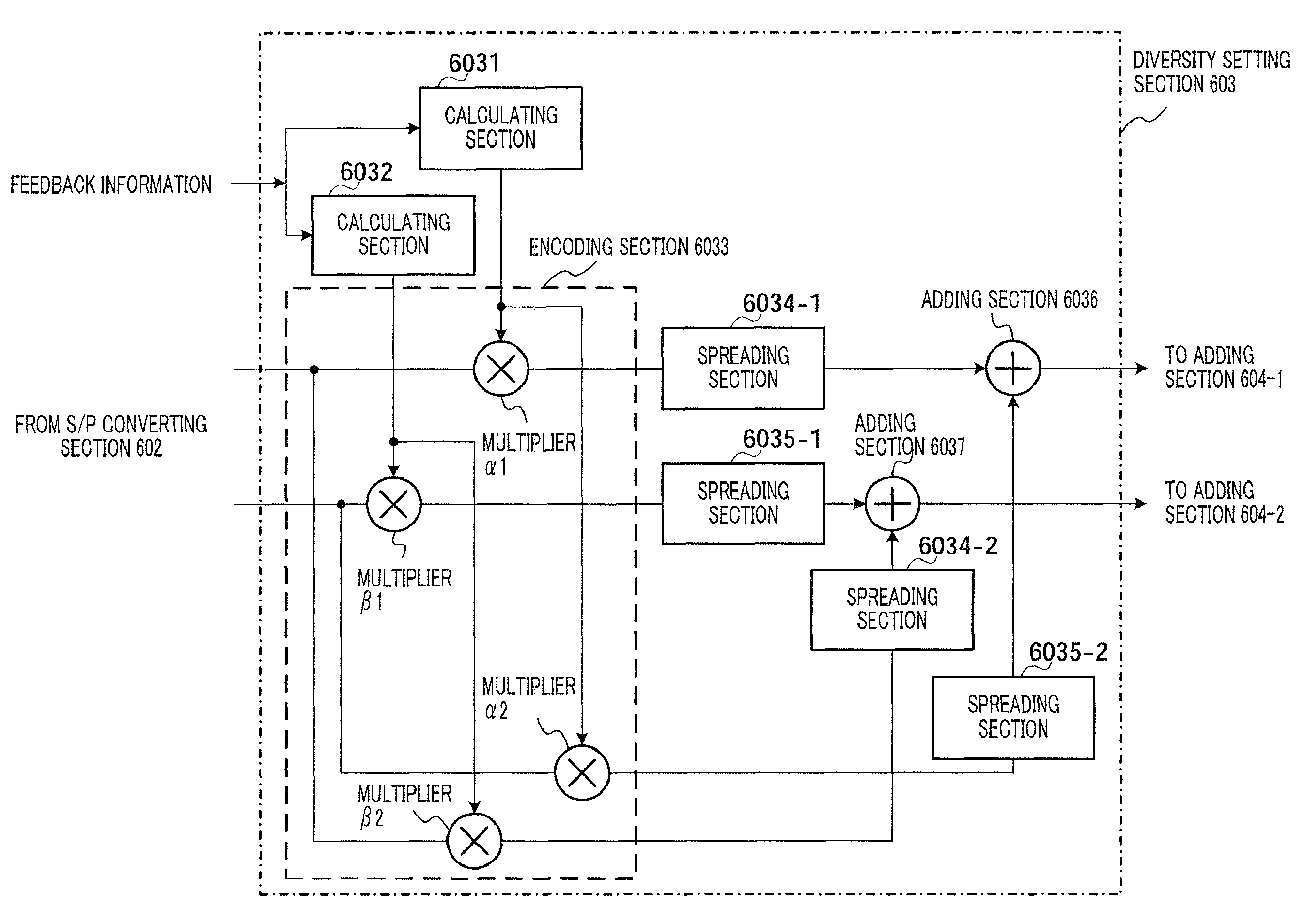
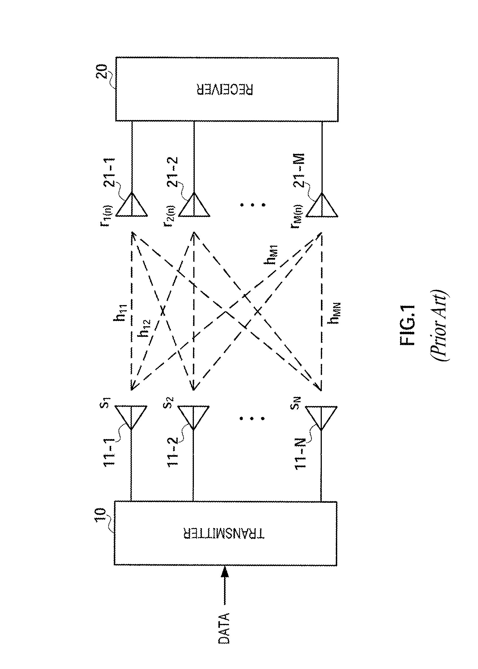
[0041]An embodiment of the present invention will be described in detail below with reference to the accompanying drawings. For ease of explanation of the present invention, unnecessary detailed configurations and functions will be omitted. Further, for ease of explanation, in this embodiment, the number of transmitting antennas is assumed to be two, and the number of receiving antennas is assumed to be one.

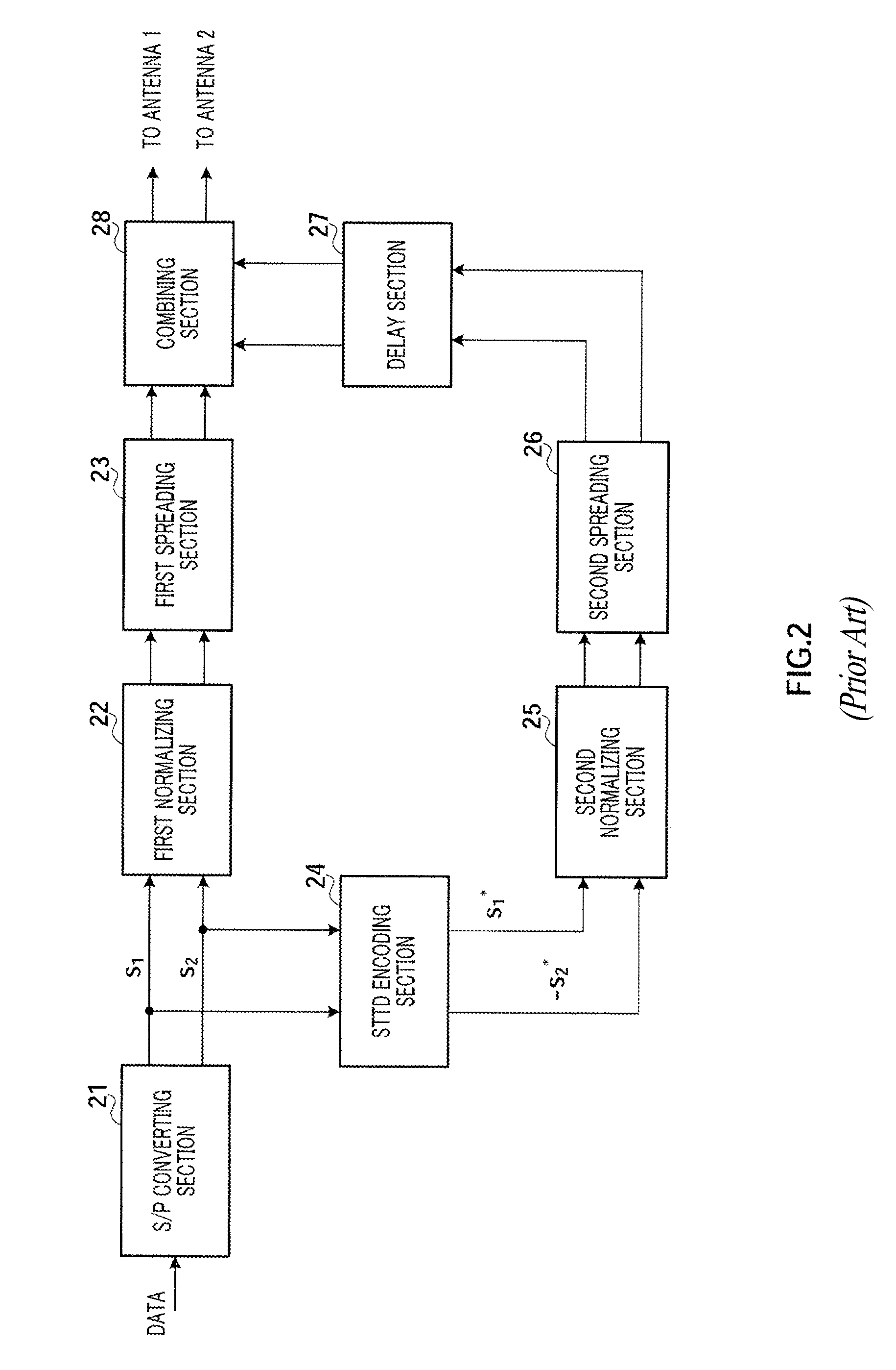
[0042]Generally, when two symbols are transmitted in one period to improve the transmission rate of the system, the receiving side requires two or more equations to decode the two symbols. Even in the case of flat fading, to obtain two or more equations, the receiving side needs to provide two or more diversity branches. On the other hand, when data is spread, if two spreading codes are distributed to one user, the receiving side can decode two symbols transmitted at the same time utilizing the feature that the two spreading codes are orthogonal to each other. However, when two s...


PUM


Abstract

A wireless communication apparatus in a closed loop communication wherein a channel resource can be shared among users and hence the capacity of the communication system can be increased. In this apparatus, calculating parts (6031 and 6032) calculate a first pre-code (α) and a second pre-code (β), respectively, from CSI fed back from a receiving wireless communication apparatus; an encoding part (6033) includes multipliers (α1, α2), which multiply the first pre-code (α) by a first data and a second data to generate a first encoded data and a third encoded data, respectively, and also includes multipliers (β1, β2) that multiply the second pre-code (β) by the first data and the second data to generate a second encoded data and a fourth encoded data, respectively; spreading parts (6034-1 and 6034-2) spread the first and second encoded data with a first spreading code (c) to generate a first spread data and a second spread data, respectively; spreading parts (6035-1 and 6035-2) spread the third and fourth encoded data with a second spreading code (p) to generate a third spread data and a fourth spread data, respectively; an adding part (6036) adds the first spread data and the third spread data together; and an adding part (6037) adds the second spread data and the fourth spread data together.

Description

TECHNICAL FIELD[0001]The present invention relates to a wireless communication apparatus and wireless communication method. More particularly, the present invention relates to a wireless communication apparatus and wireless communication method used in a closed-loop MIMO (Multi Input Multi Output) communication system.BACKGROUND ART[0002]The space multiplexing MIMO communication system transmits signals using multiple antennas of the receiving side and the transmitting side, and provides a feature of high throughput. FIG. 1 shows a configuration of the conventional MIMO communication system. As shown in FIG. 1, in the space multiplexing MIMO communication system, transmitter 10 transmits different symbol sequences s1, s2 . . . , sN through transmitting antennas 11-1 to 11-N, respectively, at the same time, in the same symbol period, and receiver 20 receives the signals using receiving antennas 21-1 to 21-M. Channel fading between transmitting antennas 11-1 to 11-N and receiving ante...

Claims


Application Information

Patent Timeline
Patent Type & Authority Patents(United States)
IPC IPC(8): H04B1/00H04L27/00H04J99/00H04B1/707
CPCH04B7/0626H04L1/0618H04L1/0006H04B1/7115H04B17/382
Inventor ZHAO, ZHENGLI, JIFENG
Owner PANASONIC CORP
Why Eureka
Try Eureka