
Disconnect sensor

a sensor and disconnection technology, applied in the field of sensors, can solve problems such as limiting the control of the aircraft, skewing of the surface that the actuator drives, and affecting the flight of the aircraft, and achieve the effect of reducing the risk of skewing and disconnection

Active Publication Date: 2011-04-12
HAMILTON SUNDSTRAND CORP
View PDF17 Cites 30 Cited by
  • Summary
  • Abstract
  • Description
  • Claims
  • Application Information

AI Technical Summary

Problems solved by technology

Such misaligned movement is called “skew.” If one of the actuators fails, skew of the surface that the actuator drives may occur.
This skew may jam a control surface mechanism, thereby restricting control of the aircraft.
A surface may jam if the forces on the surface are asymmetrical.
If both actuators driving the same surface fail, the surface may separate from the wing and be lost.
A single actuator can be used to actuate a control surface; however, this method does not supply the desirable redundancy that multiple actuators afford.
Use of multiple actuators, however, requires synchronization, which requires additional complexity.
One disadvantage with this traditional sensor is that it can be unreliable under certain conditions.
Further, it is difficult to assemble and requires different parts to be incorporated into right hand and left hand wing positions.
The reed switch may fail in the closed position, a failure mode which is not detected by the control unit.
This fault may go undetected on the aircraft until maintenance personnel perform a manual check of each sensor, which typically occurs during an aircraft level periodic maintenance interval.

Method used


Image

  • Disconnect sensor
  • Disconnect sensor
  • Disconnect sensor

Examples


Embodiment Construction

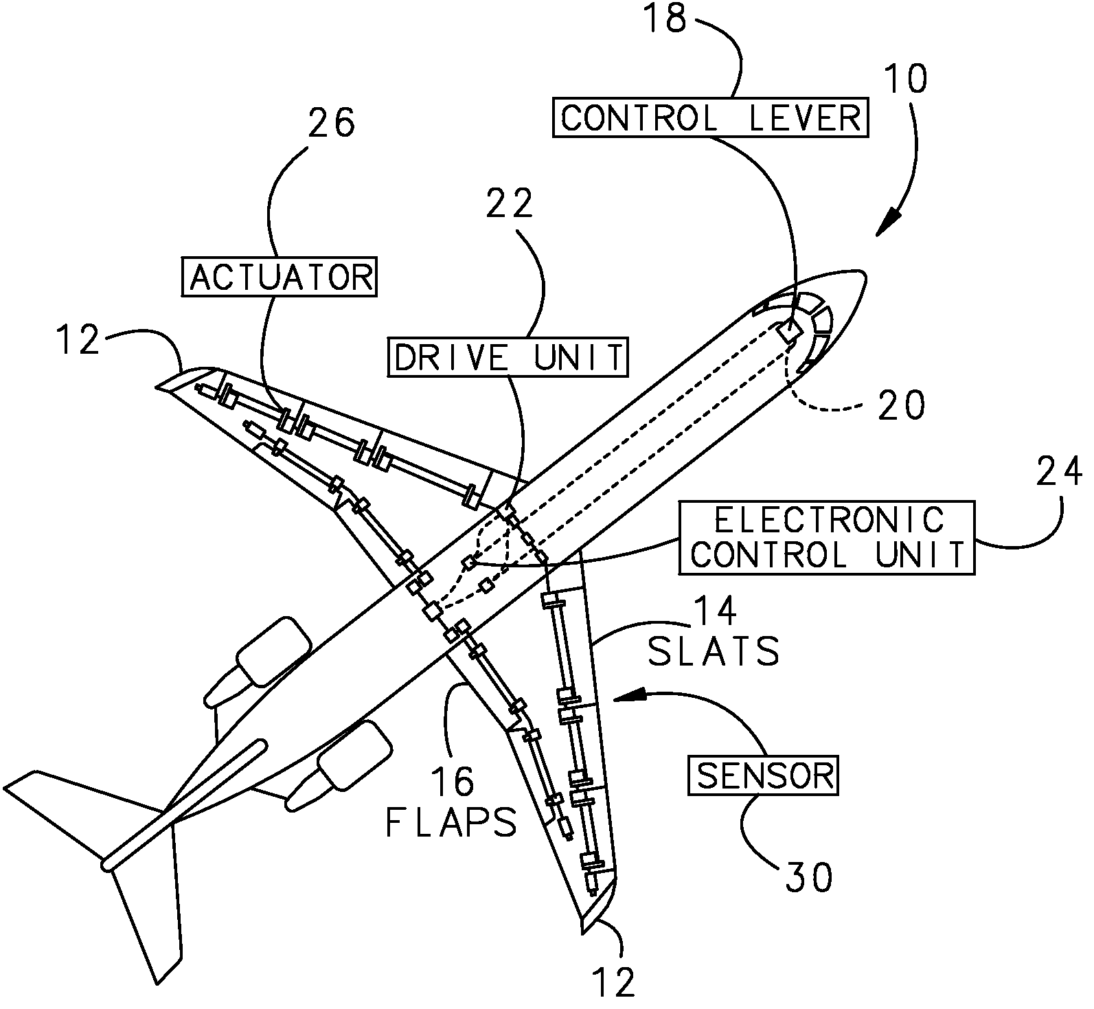
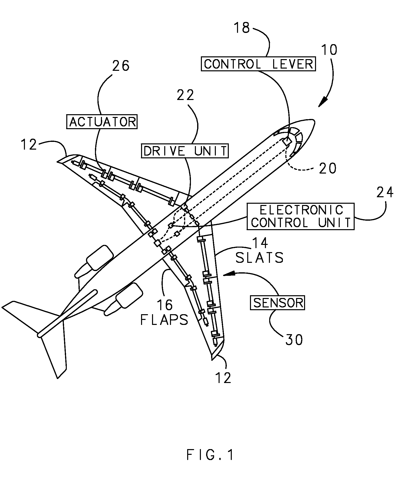
[0026]FIG. 1 illustrates a typical aircraft 10 that has two wings 12, each having a plurality of control surfaces, such as slats 14 and flaps 16. These control surfaces are movable surfaces to control lift. In one example, a control lever 18 for the slats 14 and flaps 16 is located in a cockpit 20. A drive unit 22 controlled by an electronic control unit 24 transmits torque to a plurality of actuators 26, which may be used to drive slats 14 or flaps 16. A sensor 30 is attached between adjacent control surfaces to sense relative movement between adjacent control surfaces.

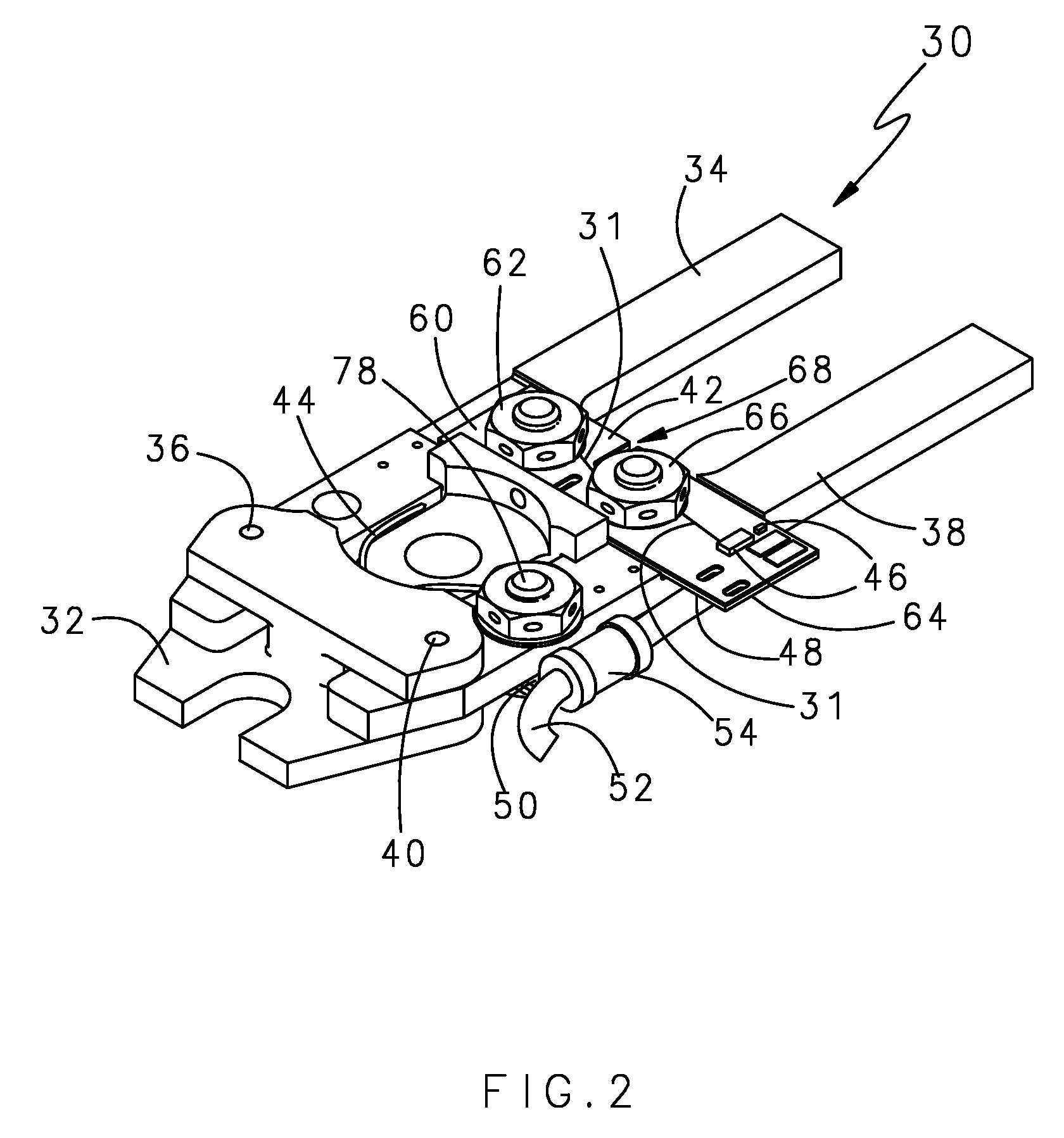
[0027]FIG. 2 illustrates an example of the sensor 30. The sensor 30 includes a base 32, a first arm 34 pivotally connected to the base 32 with a first pin 36, a second arm 38 pivotally connected to the base 32 with a second pin 40, and an electrical connecting element that is attached to the first 34 and second 38 arms. In the example shown, the electrical connecting element comprises a circuit board 42; however othe...


PUM

PropertyMeasurementUnit
movementaaaaaaaaaa
direct currentaaaaaaaaaa
currentaaaaaaaaaa

Abstract

A sensor assembly for sensing relative movement between adjacent panels includes a base and first and second arms pivotally mounted to the base. An electrical connecting element is attached to the first and second arms and holds the first and second arms in a first position to indicate a first condition. When the first and second arms have moved relative to each other by a predetermined amount, the electrical connecting element breaks to indicate a second condition.

Description

BACKGROUND OF THE INVENTION[0001]This disclosure relates to a sensor that detects skewed or disconnected adjacent movable components, and more particularly to a sensor that detects skewed or disconnected aircraft control surfaces such as slats or flaps, for example.[0002]Aircraft wings employ high-lift devices that are often referred to as auxiliary airfoils or control surfaces. During takeoff and landing of the aircraft, a pilot can extend these control surfaces from a leading or a trailing edge of a wing to increase aerodynamic lift. When extended, the surfaces increase the effective size, curvature, camber, and area of the wing. This extension increases the lift of the wing for slow-speed flight. Control surfaces that extend from the leading edge of the wing are referred to as slats, while control surfaces that extend from the trailing edge of the wing are referred to as flaps. Slats are used primarily to increase lift at large angles of attack, while flaps are designed primarily...

Claims


Application Information

Patent Timeline
Patent Type & Authority Patents(United States)
IPC IPC(8): G01L1/00
CPCB64D45/0005B64D2045/001
Inventor CONNER, PATRICK D.BAINES, ANDREW N.LEDEN, WILLIAM E.MASSOLLE, DALE W.JONES, TEDDY L.WAVERING, JEFFREY T.
Owner HAMILTON SUNDSTRAND CORP
Learn More