Side window roller blind with hinged pull rod and rectangular support rod

a technology of roller blinds and hinges, applied in the field of roller blinds, can solve the problems of unattractiveness and the possibility of using such winding shafts

Inactive Publication Date: 2011-03-01
BOS
View PDF41 Cites 16 Cited by
  • Summary
  • Abstract
  • Description
  • Claims
  • Application Information

AI Technical Summary

Benefits of technology

[0005]It is an object of the present invention to provide a roller blind for a side window of a motor vehicle which can be advantageously used in conjunction with conical winding shafts without the danger of creating slanted folds in the shade when in an extended position.
[0008]With the aid of the novel arrangement of the present invention, it is possible to use side window roller blinds with conical winding shafts. Conical winding shafts are primarily required if the upper edge of the window does not run parallel to the lower edge of the window, and the pull rod is nonetheless intended to run as parallel to the lower edge of the window as possible in the retracted state in order to be as inconspicuous as possible. With such side window roller blind configurations, the pull rod consequently undergoes a pivoting motion during the extension of the shade. By using articulations between the support rods and the pull rod, these pivoting motions can be absorbed without further effort and without creating significant tensions. When two support rods are used in such arrangement, they can have different effective lengths, depending on the requirements.
[0009]The guide mechanism inside the door body can extend over the entire extension length, or only over a part of it, i.e., the upper area. Extension of the guide mechanism over the entire range of movement has the advantage that any possibility of lateral bending inside the door under pressure stress is prevented. Furthermore, such a guide mechanism allows easier articulation of a tensioning or compressing means that is used to move the support rod, since a lateral force also naturally results from these tensioning or compressing means due to the asymmetrical force induction.

Problems solved by technology

In particular, it is considered unattractive if any slanted folds appear in the shade.
Also problematic in the known roller blinds are conical winding shafts.
Heretofore, it has only been possible to use such winding shafts in connection with manually operated window roller blinds.

Method used


Image

  • Side window roller blind with hinged pull rod and rectangular support rod
  • Side window roller blind with hinged pull rod and rectangular support rod
  • Side window roller blind with hinged pull rod and rectangular support rod

Examples


Embodiment Construction

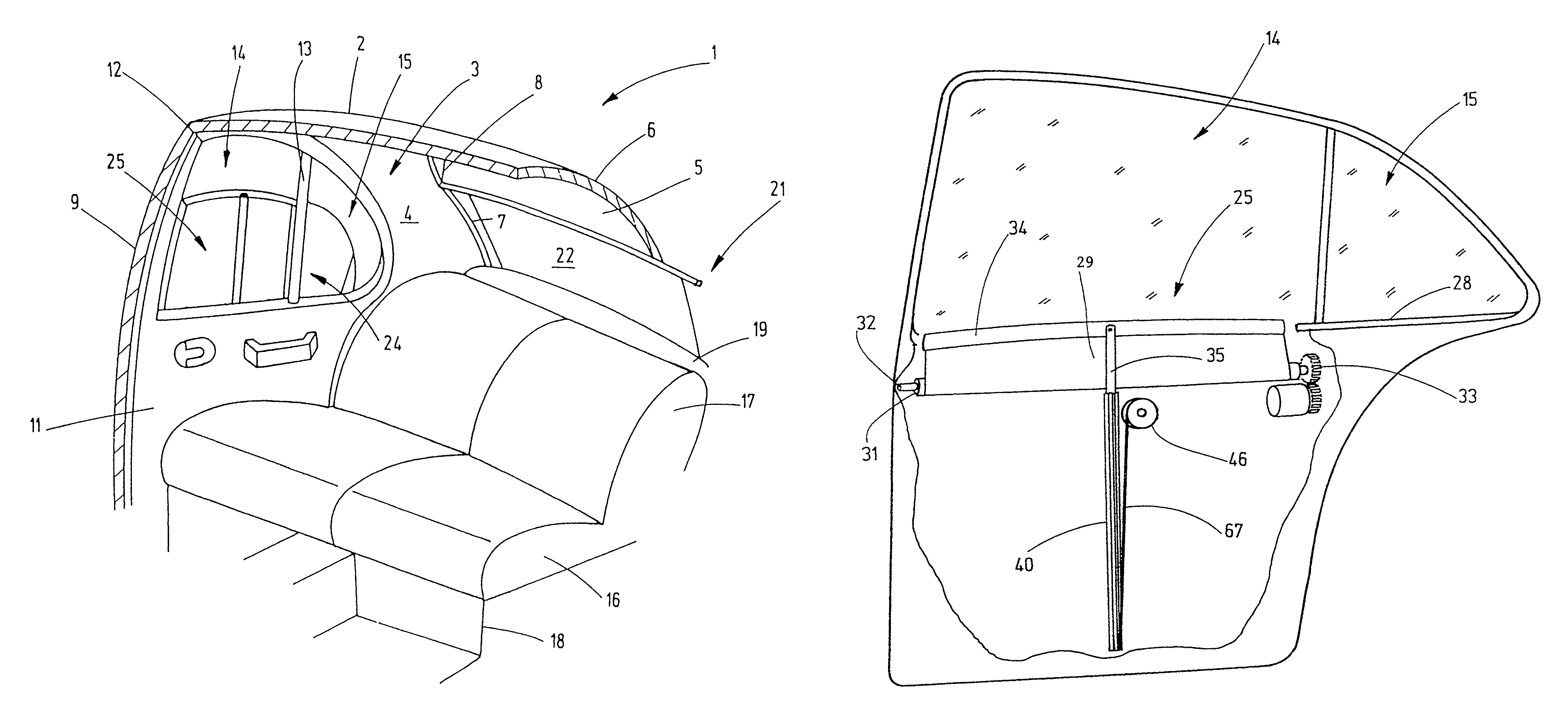
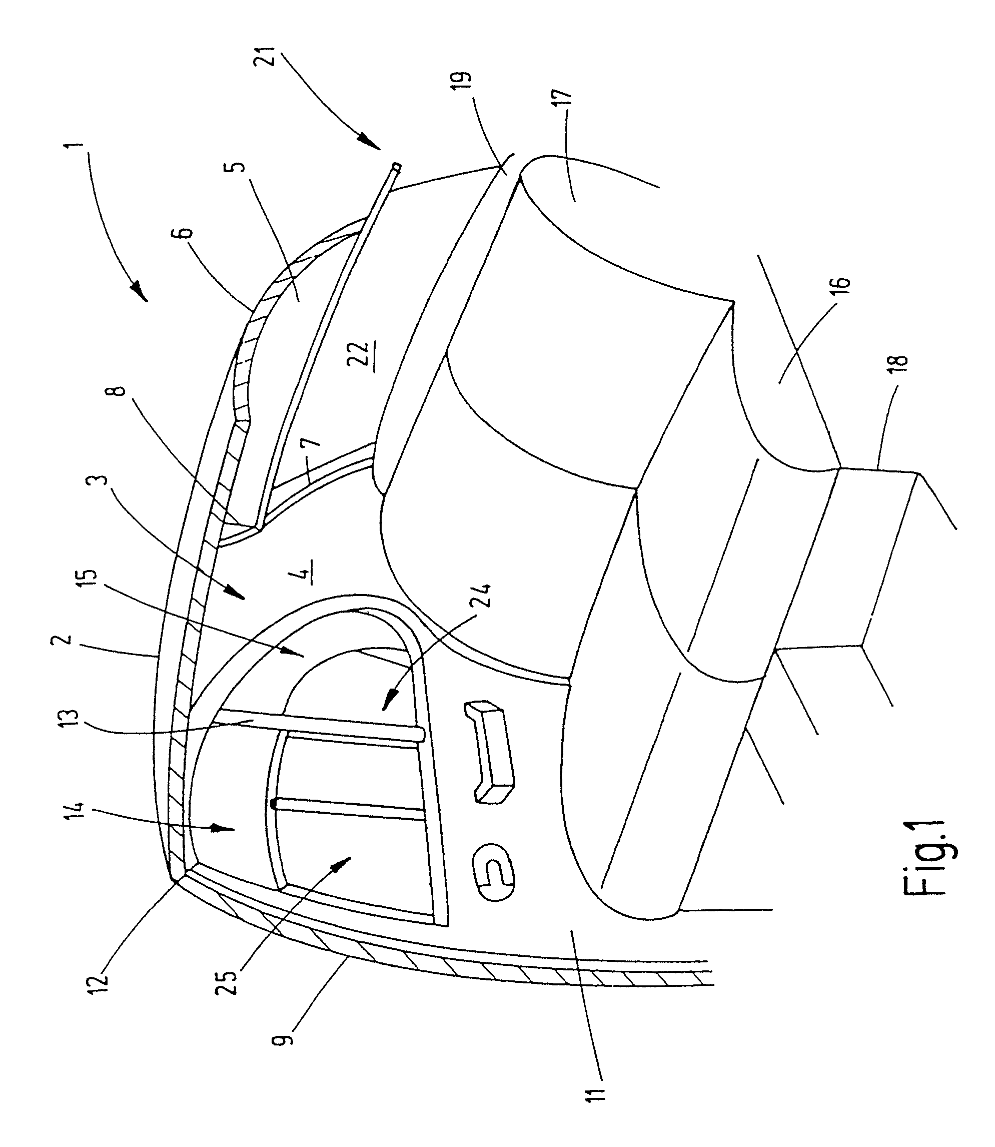
[0019]Referring now more particularly to FIG. 1 of the drawings, there is shown the rear area of a passenger car having a side window roller blind in accordance with the invention. The figure illustrates a view onto the right interior side, which is a mirror image of the broken-away left interior side. Unless otherwise indicated, the explanations for the right body side apply accordingly to the left body side as well. The representation is simplified; for instance, structures inside the bodies such as reinforcements and fastening means are not shown, since a representation thereof is not required for understanding the invention.

[0020]The illustrated vehicle has a body section 1 that comprises a roof 2 from which a C-column 3 extends laterally downward to a bottom group, not shown. A corresponding C-column exists on the opposite broken away side of the vehicle. The C-column 3 is furnished on its inner side with an inside trim panel 4.

[0021]A roof 2 transitions at its rear edge into a...


PUM


Abstract

A window roller blind that has a shade, the free end of which is connected to a pull rod. In order to guide movement of the pull rod during extension and retraction of the roller blind, a support rod is connected to pull rod by means of articulated connection.

Description

FIELD OF THE INVENTION[0001]The present invention relates generally to window roll-up shades, and more particularly, to roll-up shades for the side windows of motor vehicles.BACKGROUND OF THE INVENTION[0002]The current trend for side window roller blinds of motor vehicles is to conceal the guide mechanisms for guiding the roller blind as much as possible. Thus, the previously used guide rails running on the sides of the rectangular part of the window must be replaced by guide or support rods. When the roller blind is deployed, the support rods, as their name implies, support the pull rod that is arranged at the free end of the shade. It thus takes on two functions, namely, guiding the pull rod such that it remains against the window and generating the necessary thrust to unwind shade from the winding shaft and keep it under tension.[0003]The pull rod that is mounted at the free upper end of the support rod is intended to distribute the force exerted by the pull rod uniformly onto th...

Claims


Application Information

Patent Timeline
Patent Type & Authority Patents(United States)
IPC IPC(8): B60J3/00A47H5/00A47H1/00
CPCB60J1/2033B60J1/2086B60J1/2044E06B9/68B60J3/02B60J1/20
Inventor HANSEN, MELF
Owner BOS
Why Eureka
Try Eureka