
Sliding door grab bar opener

a door handle and sliding glass door technology, applied in the direction of wing knobs, wing accessories, manufacturing tools, etc., can solve the problems of difficult operation of existing door handles on sliding glass doors, particularly troubling older people, etc., and achieve the effect of convenient opening and closing

Inactive Publication Date: 2011-01-04
NOTTAGE JAMES T
View PDF25 Cites 7 Cited by
  • Summary
  • Abstract
  • Description
  • Claims
  • Application Information

AI Technical Summary

Benefits of technology

[0005]It is an object of the present invention to provide a grab bar opener for sliding doors that provides a visual cue as to the door configuration, and provides a means to allow the door to be more easily opened and closed with the use of both hands.

Problems solved by technology

Persons entering or leaving a room through a sliding glass door can sometimes mistakenly think that the door is open when it is in fact closed, and bump into it which can cause injury.
This can be particularly troubling to older people who are in a wheel chair or other wheeled transport device.
Existing door handles on sliding glass doors can sometimes be difficult to operate, particularly for older people.

Method used


Image

  • Sliding door grab bar opener
  • Sliding door grab bar opener
  • Sliding door grab bar opener

Examples


Embodiment Construction

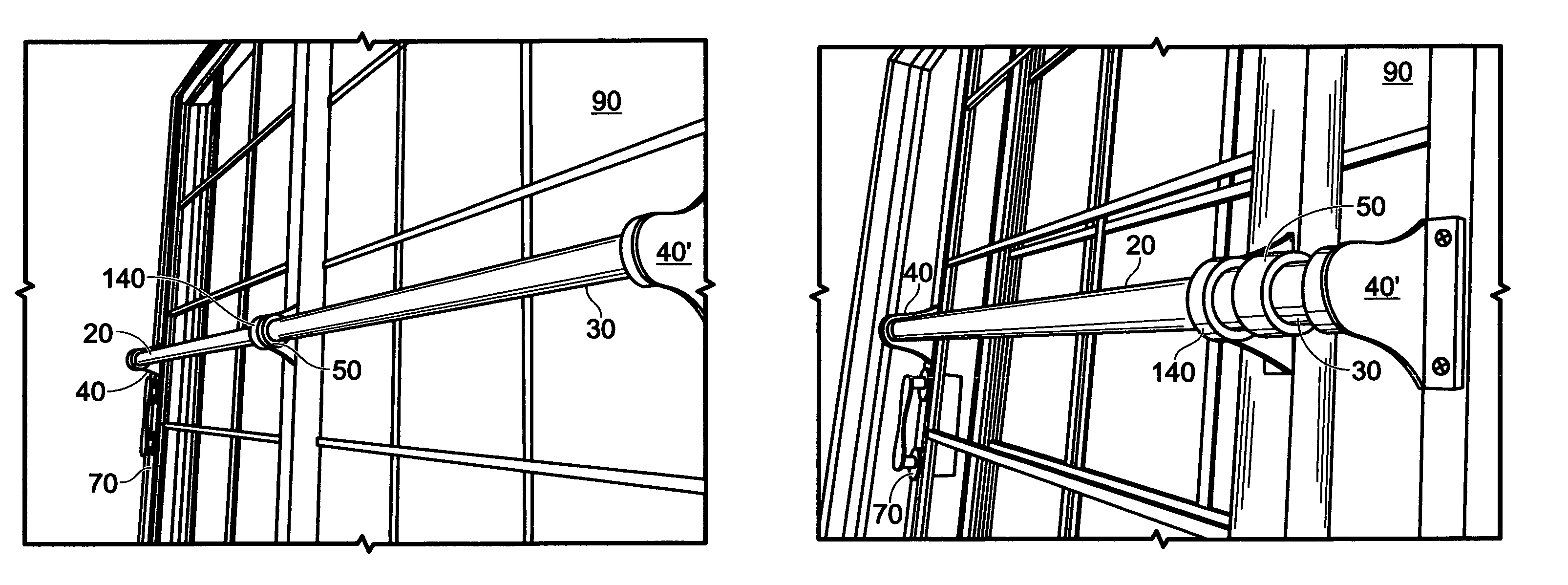
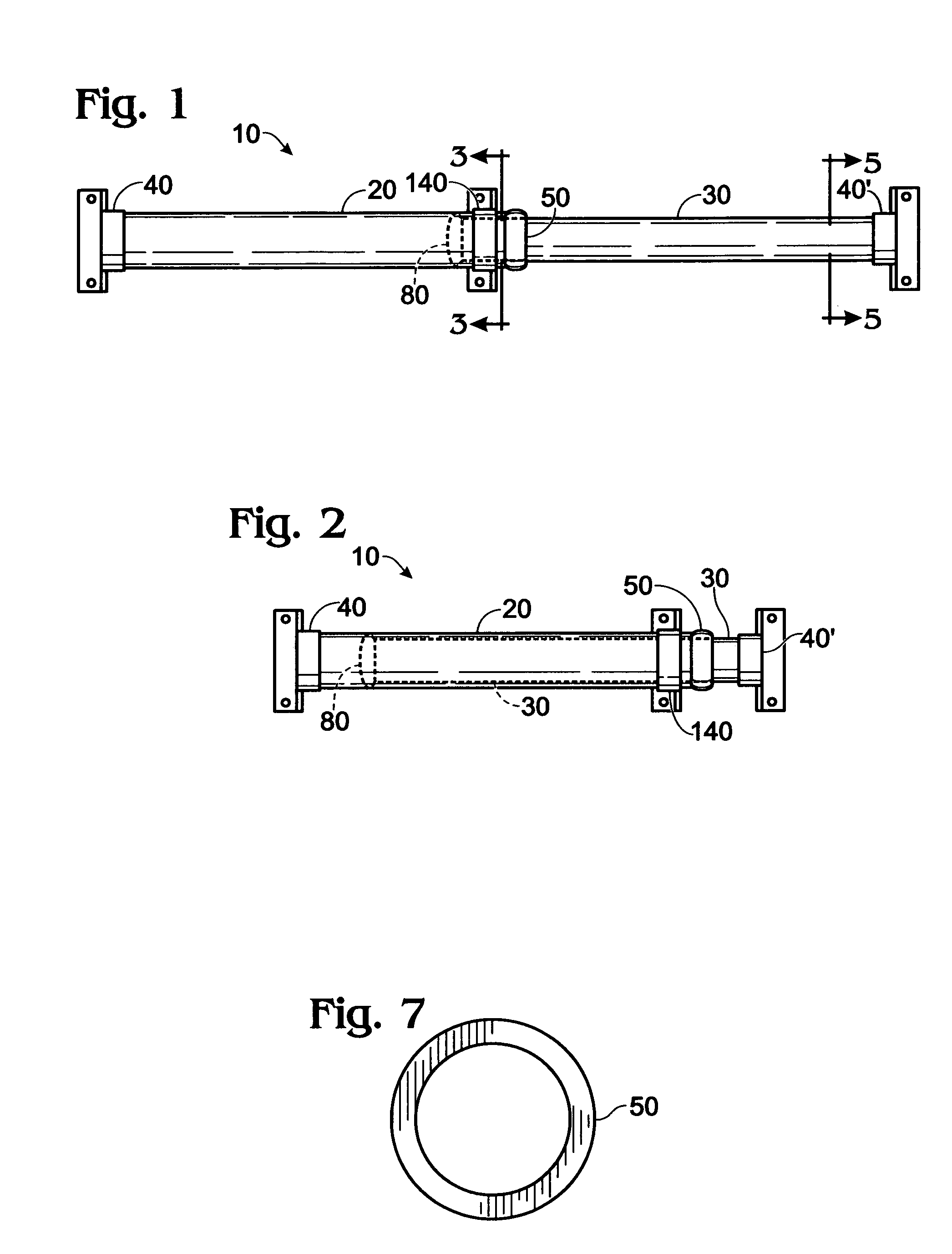
[0018]Grab bar opener 10 includes an outside tube member 20 and an inside tube member 30. The outer diameter of inside tube member 30 is slightly smaller than the inner diameter of outside tube member 20. Inside tube member 30 is adapted to be received within outside tube member 20 and to slide between a fully extended configuration shown in FIG. 1 to a fully retracted configuration shown in FIG. 2. Outside tube member 20 and inside tube member 30 have a common longitudinal axis.

[0019]The first, outer end of outside tube member 20 is attached to a first end stanchion member 40, and the second, inner end of outside tube member 20 is attached to a dust cover 50.

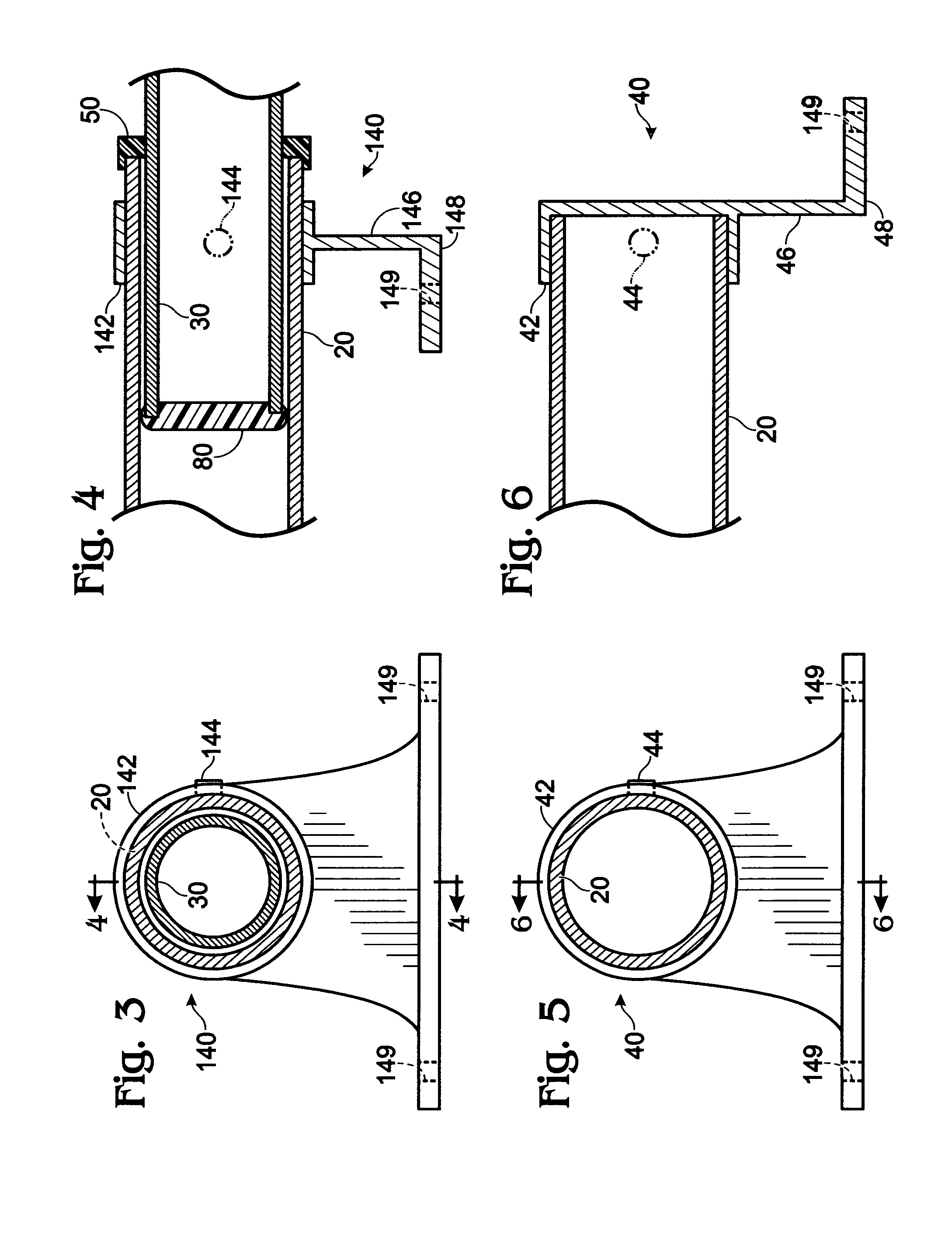
[0020]As best seen in FIGS. 5 and 6, first end stanchion member 40 includes a collar portion 42 which fits over outside tube member 20 and is attached thereto by any suitable means, such as set screw 44. An L-shaped attachment bracket extends from collar portion 42 and has a first leg 46 and a second leg 48. First leg 46 has a ...


PUM


Abstract

A sliding door grab bar opener for opening and closing a sliding door. The opener includes outside and inside tube members, each having first and second ends. The inside tube member is positioned within the outside tube member and is adapted to slide from a fully retracted configuration with the first end of the inside tube member being located adjacent the first end of the outside tube member to a fully extended configuration with the first end of the inside tube member being located adjacent the second end of the outside tube member. First and second end stanchion members are attached to the outside and inside tube members adjacent their first and second ends, respectively. A middle stanchion member is attached to the outside tube member adjacent its second end. The stanchion members are adapted to be attached to the frames of the sliding door panels by fastener means.

Description

CROSS-REFERENCE TO RELATED APPLICATIONS[0001]This application claims the benefit of U.S. Provisional Application No. 60 / 951,642, filed Jul. 24, 2007, the entire contents of which are hereby incorporated by reference.BACKGROUND OF THE INVENTION[0002]The present invention relates to a sliding door grab bar opener.[0003]Persons entering or leaving a room through a sliding glass door can sometimes mistakenly think that the door is open when it is in fact closed, and bump into it which can cause injury. This can be particularly troubling to older people who are in a wheel chair or other wheeled transport device.[0004]Existing door handles on sliding glass doors can sometimes be difficult to operate, particularly for older people.SUMMARY OF THE INVENTION[0005]It is an object of the present invention to provide a grab bar opener for sliding doors that provides a visual cue as to the door configuration, and provides a means to allow the door to be more easily opened and closed with the use ...

Claims


Application Information

Patent Timeline
IPC IPC(8): E05B1/00E05D15/06
CPCE05B1/0015Y10T16/498Y10T16/473E05B65/08
Inventor NOTTAGE, JAMES T.
Owner NOTTAGE JAMES T
Learn More