
Transmitting device, receiving device and method for establishing a wireless communication link

a wireless communication and transmitting device technology, applied in the direction of digital transmission, data switching networks, wireless communication, etc., can solve the problems of specific transmission paths, channel quality may be reduced, and the corresponding channel quality of the associated transmission path may not be sufficient for the transmitting device, so as to achieve fast link establishment, good and reliable transmission quality, and simple but very effective and reliable

Inactive Publication Date: 2010-12-28
SONY DEUT GMBH
View PDF8 Cites 4 Cited by
  • Summary
  • Abstract
  • Description
  • Claims
  • Application Information

AI Technical Summary

Benefits of technology

"The present invention provides a method and device for establishing a wireless communication link between two devices with narrow beam antennas. The invention addresses the issue of poor channel quality and obstacles that may block the communication link. The method involves transmitting a link request signal from the transmitting device to the receiving device via the narrow beam antenna, and the receiving device determining the channel quality of the transmission path. The narrow beam antenna is then steered to different positions, and the process repeated until a suitable transmission path is found. The invention simplifies the process of establishing a wireless communication link between the two devices."

Problems solved by technology

For this particular position of the narrow beam antenna of the transmitting device, the corresponding channel quality of the associated transmission path may not be sufficient for the receiving device to receive a link request signal transmitted from the transmitting device.
For example, there might be an obstacle blocking this specific transmission path or channel quality might be decreased for other reasons.
The situation is even worse when both the transmitting device and the receiving device each comprise a narrow beam antenna which can be steered to different positions.
At the moment at which the transmitting device tries to establish a communication with the receiving device, both narrow beam antennas might be totally misaligned so that the receiving device might not even receive any signal.

Method used


Image

  • Transmitting device, receiving device and method for establishing a wireless communication link
  • Transmitting device, receiving device and method for establishing a wireless communication link
  • Transmitting device, receiving device and method for establishing a wireless communication link

Examples


Embodiment Construction

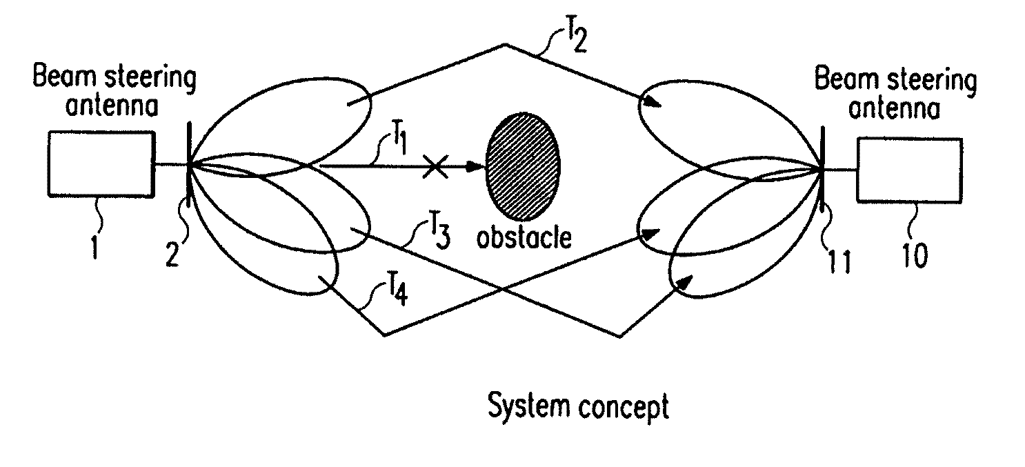
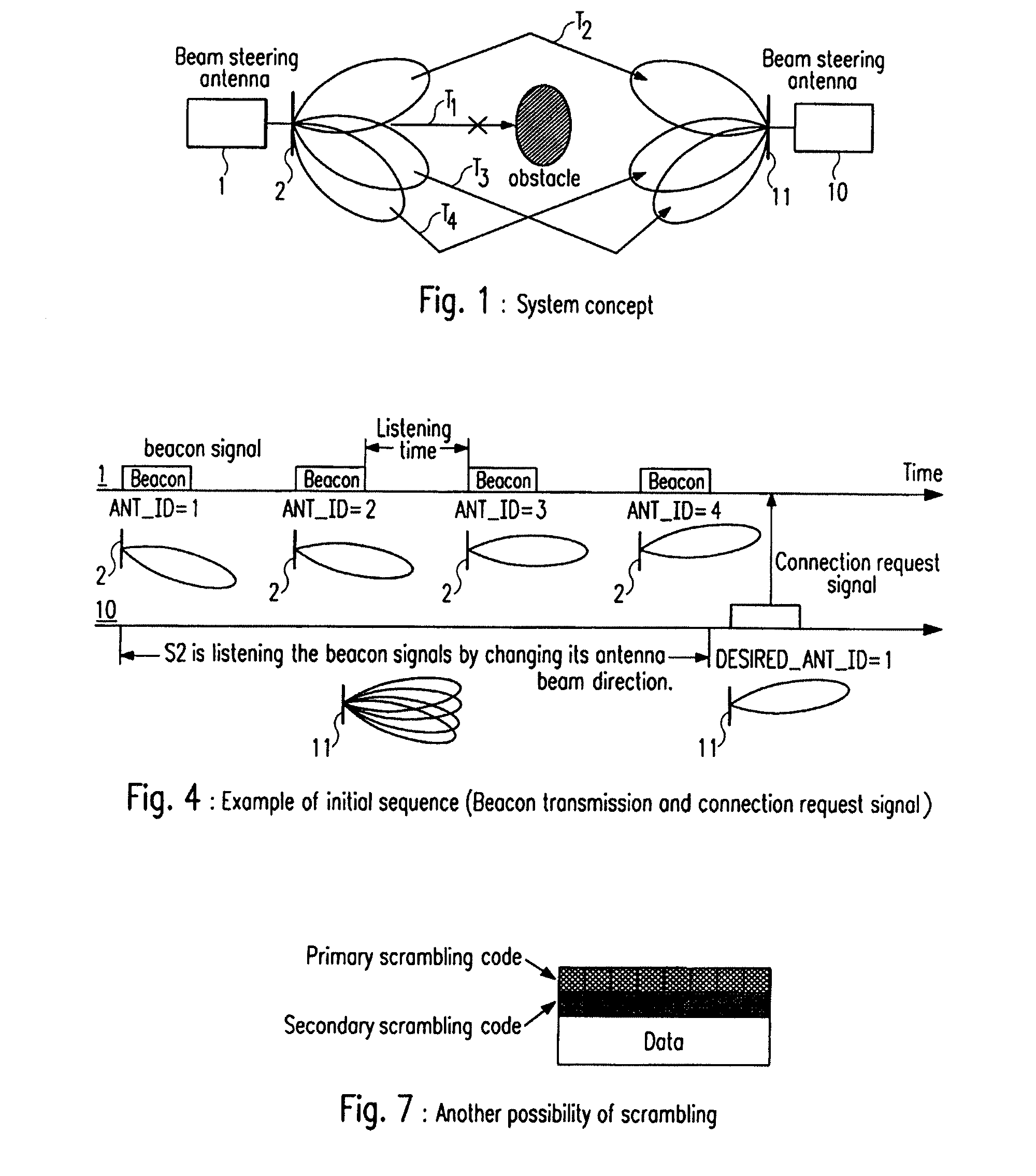
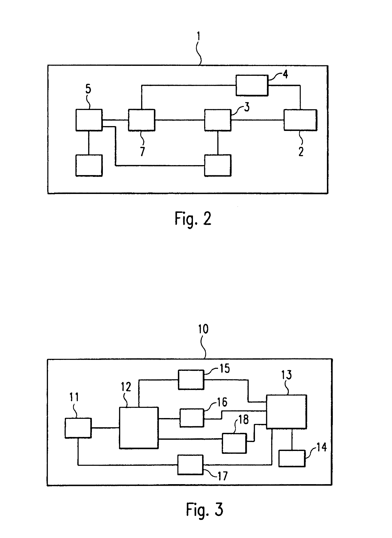
[0032]FIG. 1 schematically shows how a communication link between a transmitting device 1 and a receiving device 10 according to the present invention is established. The transmitting device 1 will be explained in more detail in relation to FIG. 2. The receiving device 10 will be explained in more detail in relation to FIG. 3.

[0033]The transmitting device 1 comprises a narrow beam antenna 2 which is adapted to be steered into different positions as shown in FIG. 1. In the example shown in FIG. 1, the receiving device 10 also has a narrow beam antenna 11 which is adapted to be steered to different positions. However, according to the present invention, the receiving device 10 may also have a wide beam or omni-directional antenna, which cannot be steered to a predominant beam position. In the example shown in FIG. 1, the narrow beam antennas 2 and 11 can be steered to different positions, so that a number of different transmission paths T1, T2, T3 and T4 between the transmitting devic...


PUM


Abstract

A method for establishing a wireless communication link between a first communication device having a beam antenna to be steered to different positions and a second communication device. The method includes transmitting a link request signal from the first communication device to the second communication device via the beam antenna. The link request signal includes information relating to a current position of the beam antenna. The method further includes obtaining, in case the link request signal is received in the second communication device, channel quality information representative of a current transmission path.

Description

CROSS-REFERENCE TO RELATED APPLICATIONS[0001]This application is a continuation of and is based upon and claims the benefit of priority under 35 U.S.C. §120 for U.S. Ser. No. 11 / 865,366, filed Oct. 1, 2007, the entire contents of this application is incorporated herein by reference. U.S. Ser. No. 11 / 865,366 claims the benefit of priority under 35 U.S.C. § 119 from European Application No. 06 021 152.1, filed on Oct. 9, 2006.BACKGROUND OF THE INVENTION[0002]1. Field of the Invention[0003]The present invention related to a transmitting device and a receiving device for a wireless communication system, as well as to a method for establishing a wireless communication link between such a transmitting device and receiving device.[0004]2. Discussion of the Background[0005]The present invention is particularly directed to problems and solutions associated with the establishment of a communication link between a transmitting device and a receiving device for a wireless communication system, ...

Claims


Application Information

Patent Timeline
Patent Type & Authority Patents(United States)
IPC IPC(8): H04L12/56H01Q1/00H04W16/28H04W72/54
CPCH04W16/28H04W76/02H04W72/08H04W84/18H04W76/10H04W72/54
Inventor UNO, MASAHIROWANG, ZHAOCHENG
Owner SONY DEUT GMBH
Learn More