
Body-insertable device system and body-insertable device guiding method

a body-insertable device and body-insertable technology, applied in the field of body-insertable device system and body-insertable device guiding method, can solve the problems of consuming a lot of time and labor

Active Publication Date: 2010-11-30
OLYMPUS CORP
View PDF24 Cites 17 Cited by
  • Summary
  • Abstract
  • Description
  • Claims
  • Application Information

AI Technical Summary

Benefits of technology

[0006]The images picked up by the capsule endoscope during the movement of the capsule endoscope in the subject is received by an external display device by way of an antenna attached on the surface of the subject. The display device is wirelessly communicable with the capsule endoscope and capable of storing the images, and successively stores the images received from the capsule endoscope in the subject to a memory. A doctor or a nurse displays the images stored in the display device, i.e., the images of the insides of the digestive tract of the subject, and observes (examines) the insides of the subject to diagnose the subject.

Problems solved by technology

This fact indicates that much time and labor are consumed to pick up a series of images over the desired region in the digestive tract as the desired observation region, and the highly skilled doctor is tied to the guiding operation of the capsule endoscope for a long time.

Method used


Image

  • Body-insertable device system and body-insertable device guiding method
  • Body-insertable device system and body-insertable device guiding method
  • Body-insertable device system and body-insertable device guiding method

Examples


first embodiment

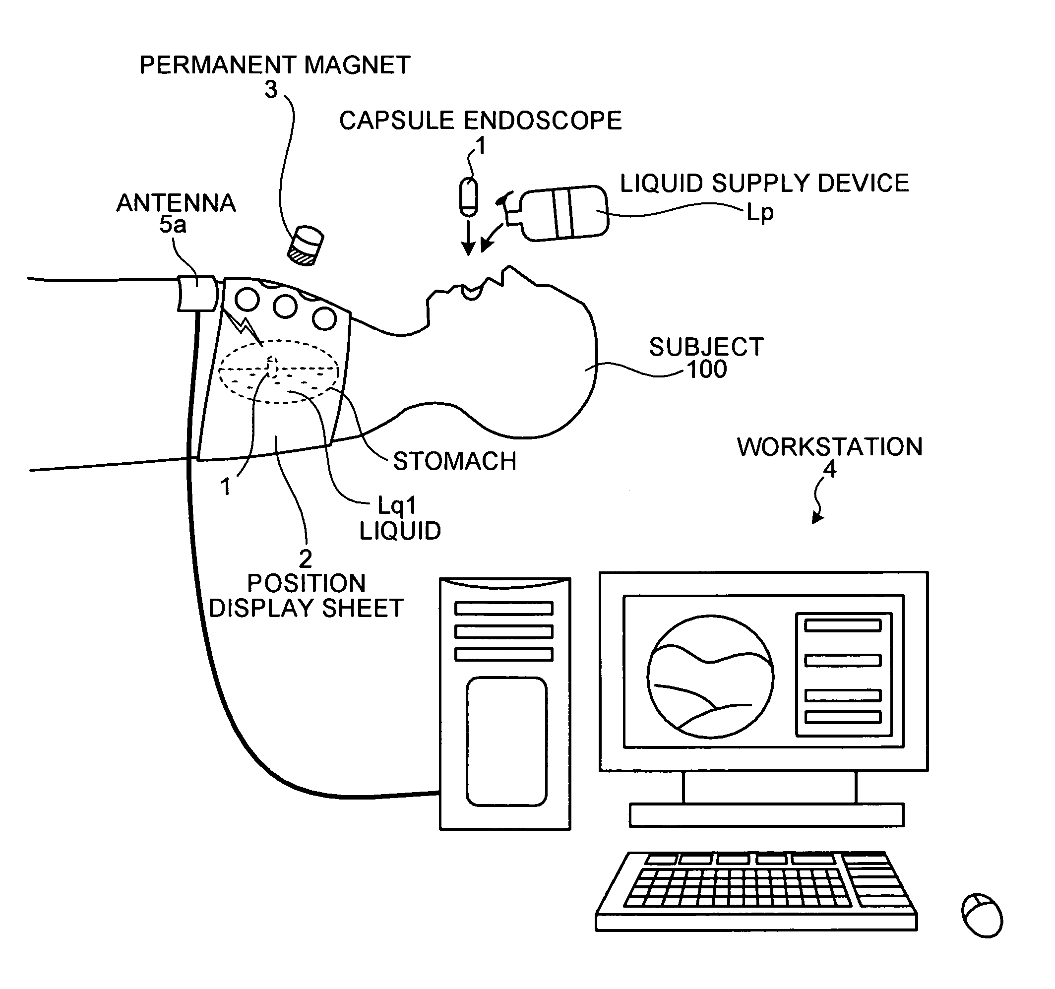
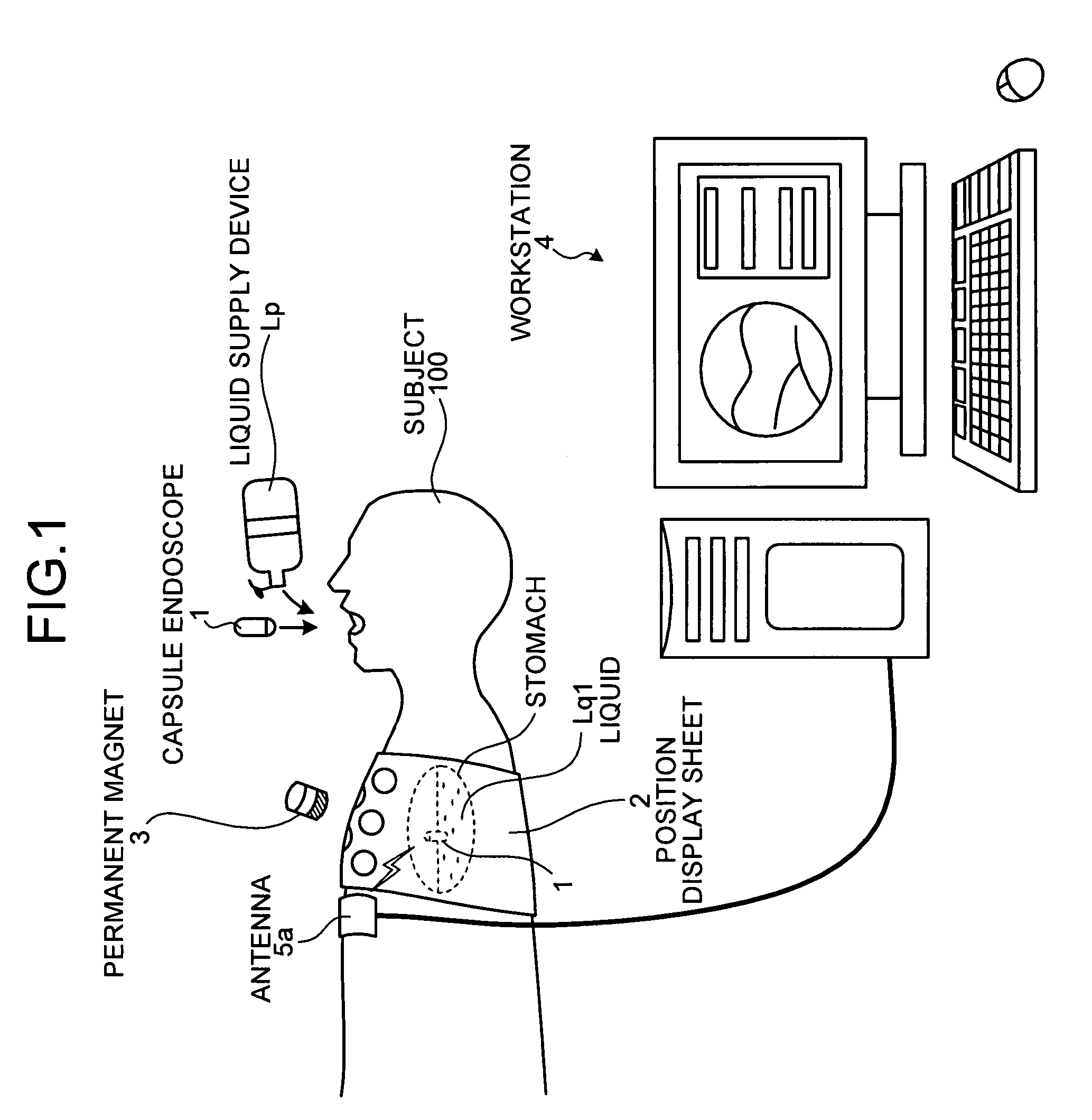
[0052]FIG. 1 is a schematic diagram showing a configuration example of a body-insertable device system in a first embodiment of the present invention. As shown in FIG. 1, the body-insertable device system of the first embodiment is made up of a capsule endoscope 1 which is introduced into a subject 100 and picks up images in an digestive tract of the subject 100, a liquid supply device Lp for supplying a liquid Lq1 for floating the capsule endoscope 1 into the subject 100, a permanent magnet 3 for controlling at least one of a position and a posture of the capsule endoscope 1 that floats in the liquid Lq1, a position display sheet 2 for visually presenting positions on the body surface of the subject to which the permanent magnet 3 is moved closer to the subject 100, and a workstation 4 for displaying images picked up by the capsule endoscope 1 on the display.

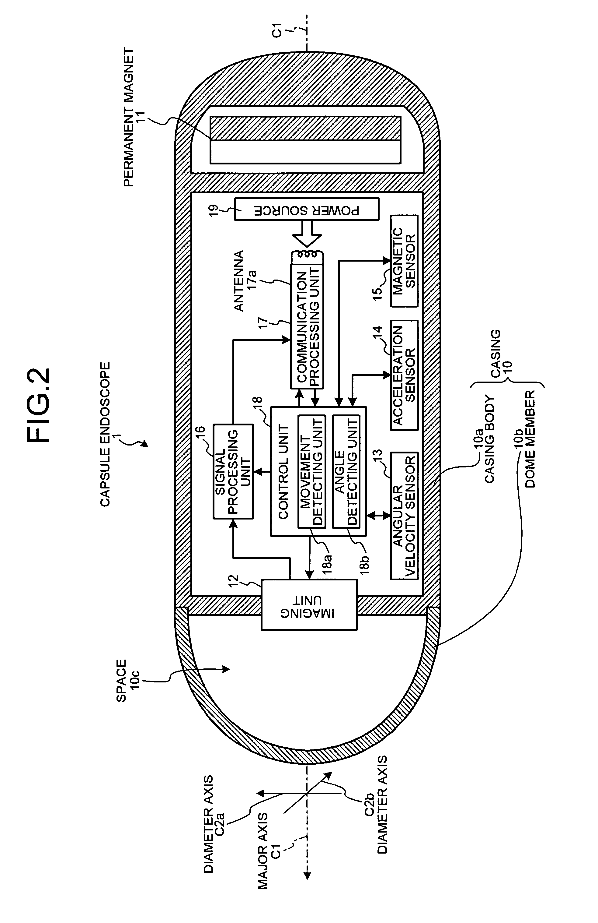
[0053]The capsule endoscope 1 has an imaging function to pick up images in the subject 100 and a radio communication function...

second embodiment

[0140]A second embodiment of the present invention will be described. As recalled, in the first embodiment, at least one of the position and the posture of the capsule endoscope 1 in the liquid Lq1 is controlled by moving the permanent magnet 3 close to the approaching position. In the second embodiment to be describe hereunder, at least one of the position and the posture of the capsule endoscope 1 in the liquid Lq1 is controlled by moving close to the approaching position an electromagnetic of which the intensity of the magnetic field is controlled by controlling the driving power.

[0141]FIG. 13 is a schematic diagram showing a configuration example of a body-insertable device system in the second embodiment of the present invention. As shown in FIG. 13, the body-insertable device system of the third embodiment includes a position display sheet 22 in place of the position display sheet 2 in the body-insertable device system of the first embodiment, a magnetic field generator 33 in ...

third embodiment

[0163]A third embodiment of the predetermined will be described. As recalled, in the first embodiment, one antenna 5a is connected to the workstation 4, and the capsule endoscope 1 and the workstation 4 wirelessly communicate with each other by way of the antenna 5a. In the third embodiment, a plurality of antennae are connected to the workstation, and the capsule endoscope 1 and the workstation wirelessly communicate with each other by way of one of the antennae.

[0164]FIG. 17 is a schematic diagram showing a configuration example of a body-insertable device system, which is an third embodiment of the present invention. As shown in FIG. 17, the body-insertable device system according to the third embodiment uses a workstation 64 in place of the workstation 4 in the body-insertable device system of the first embodiment. The workstation 64 includes an antenna group 55 in place of one antenna 5a connected to the workstation 4 in the first embodiment. The remaining arrangement is the su...


PUM


Abstract

An object of the present invention is that the examiner easily picks up a series of images over a desired region in a desired digestive tract without such troublesome examination work that the examiner successively knows the imaging field to the inside of the digestive tract. A body-insertable device system of the invention includes a capsule endoscope 1, a permanent magnet 3, and a position display sheet 2. In the capsule endoscope 1, a imaging unit for picking up the images of the insides of an subject 100, and a magnet are contained in a casing. The capsule endoscope sends a radio signal containing information of the images of the insides of the subject 100 to outside the capsule endoscope. The permanent magnet 3 generates a magnetic field for application to the capsule endoscope 1 in liquid Lq1 having been introduced into the subject 100 and changes at least one of a position and a posture of the capsule endoscope 1 by the magnetic field. The position display sheet 2 visually presents an approaching position of the subject 100 that the permanent magnet 3 approaches to generate a magnetic field.

Description

CROSS-REFERENCE TO RELATED APPLICATIONS[0001]This application is based upon and claims the benefit of priority from Japanese Patent Application No. 2005-380456, filed Dec. 28, 2005, the entire contents of which are incorporated herein by reference.BACKGROUND OF THE INVENTION[0002]1. Field of the Invention[0003]The present invention relates to a body-insertable device system which introduces a capsule type body-insertable device into a subject and acquires images of the interior of the subject picked up by the body-insertable device, and a body-insertable device guiding method.[0004]2. Description of the Related Art[0005]Recently, in the field of endoscopes, there is proposed a capsule type body-insertable device (for example, a capsule endoscope) having imaging and radio communication functions. There has been developed a body-insertable device system which acquires images in the subject by using the capsule endoscope. To observe (examine) the insides of the subject, the capsule end...

Claims


Application Information

Patent Timeline
Patent Type & Authority Patents(United States)
IPC IPC(8): A61B1/04
CPCA61B1/00158A61B1/04A61B1/041A61B1/2736A61B5/07
Inventor KAWANO, HIRONAOTAKIZAWA, HIRONOBU
Owner OLYMPUS CORP
Learn More