
Ballistic armor shield for hatch area of armored vehicle

Active Publication Date: 2010-11-16
HAMANN DARRELL
View PDF41 Cites 10 Cited by
  • Summary
  • Abstract
  • Description
  • Claims
  • Application Information

AI Technical Summary

Benefits of technology

[0015]It is a further object of this invention to provide a ballistic armor shield assembly on a Stryker armored vehicle that does not inhibit access to an engine compartment of the vehicle.

Problems solved by technology

Limitations to this design include the driver either being open to attack while driving with the hatch open and / or the driver having a limited view of his environment with blind spots while operating with the hatch closed.
Given these limitations, most military armored vehicle drivers operate the vehicle with the hatch open so that they can better view the terrain around them, and this leaves the driver totally exposed to enemy attack.
When the hatch is closed, the driver experiences blind spots when operating the armored vehicle.
If the driver is in harms way, then his entire vehicle crew and its contents are at high risk.
However, there is no protection for an operator looking out when the hatch cover is raised.
However, when the armored hatch cover is closed, the operator has no visibility through the hatch cover.
However, when the portal is open, there is no protection for personal.

Method used


Image

  • Ballistic armor shield for hatch area of armored vehicle
  • Ballistic armor shield for hatch area of armored vehicle
  • Ballistic armor shield for hatch area of armored vehicle

Examples


Embodiment Construction

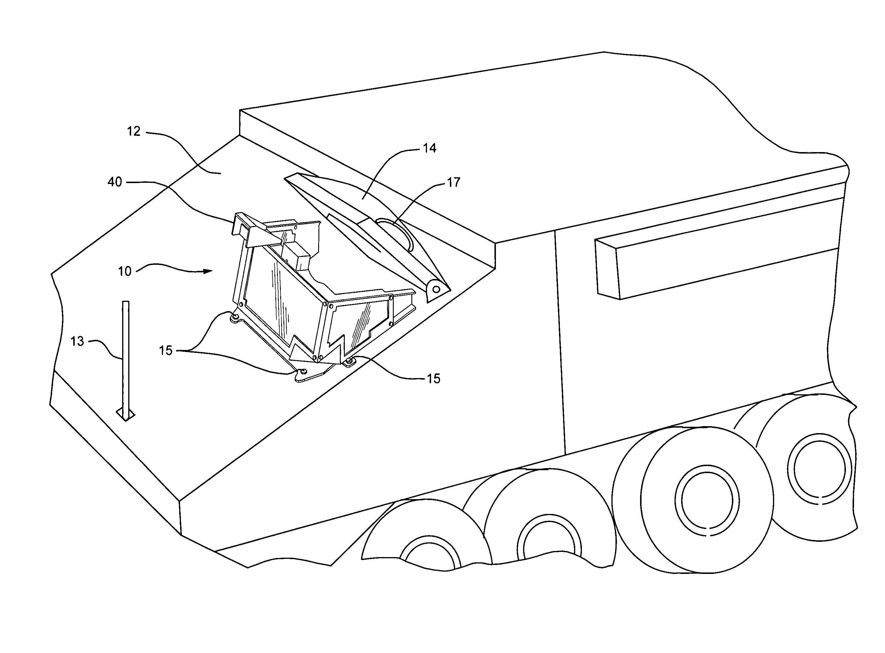
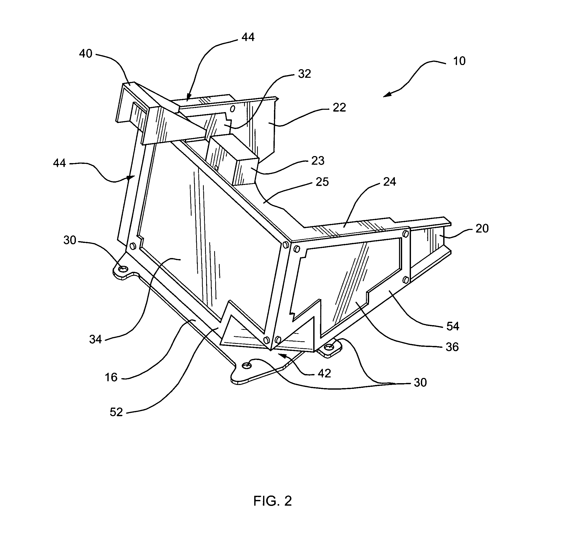
[0040]Referring to FIG. 1 and FIG. 2, FIG. 1 is a top perspective view of a ballistic armor shield assembly 10 installed around three sides of the periphery of a hatch 14 on an armored vehicle such as a Stryker armored vehicle 12, and FIG. 2 is an enlarged top perspective view of the armor shield assembly 10 according to the present invention. The ballistic armor shield assembly 10 is easily installed on the Stryker armored vehicle 12 by simply bolting it to existing holes on the armored vehicle 12 using existing bolts 15, and it provides an otherwise exposed driver with shielding on three sides and an unobstructed 270 degree view of the surrounding terrain. The armored shield works as an integrated component on the Stryker armored vehicle 12 allowing the driver to take advantage of the hatch 14 as an integrated part of the three sided armor shield assembly 10. The hatch 14 functions as the top cover of the armor shield assembly 10, giving the driver complete protection on all sides...


PUM


Abstract

A ballistic armor shield assembly attached to a Stryker armored vehicle comprises a three-sided armor shield assembly with transparent armor, which is bolted around a driver hatch directly onto the military armored vehicle using existing bolts and holes. The armor shield assembly comprises a front, left and right side armor frames forming the 3-sided assembly to which transparent armor (ballistic glass) sections are attached and secured. An enclosure is provided on the left side of the armored shield assembly for attaching and removing the entire left side transparent armor in order to facilitate vehicle engine maintenance. The driver is provided with full armor protection while operating the vehicle with his body extending out of the open hatch for improved vision. When the hatch is partially closed, the driver has full protection on the front, left, and right from the armor shield assembly as well as above from the hatch.

Description

CROSS REFERENCE TO RELATED APPLICATIONS[0001]This application claims the benefit of U.S. Provisional Application No. 60 / 759,419, filed Jan. 17, 2006, which is incorporated by reference herein in its entirety.BACKGROUND OF THE INVENTION[0002]1. Field of the Invention[0003]This invention relates generally to ballistic armor shielding for military armored vehicles operating in combat zones, hostile environments and extreme weather conditions, and in particular, to a three sided (front, left and right) ballistic armor shielding for a Stryker armored vehicle to provide the driver with maximum safety when operating the vehicle with the driver hatch open, partially open or closed.[0004]2. Description of Related Art[0005]Stryker or other military armored vehicle original designs provide for a mud shield when operating the vehicle with the hatch open, partially open, or with the hatch closed. The driver views the terrain through a periscope or small monitor from inside the vehicle. Limitatio...

Claims


Application Information

Patent Timeline
IPC IPC(8): F41H5/013
CPCF41H5/013F41H5/26F41H7/04
Inventor HAMANN, DARRELL L.
Owner HAMANN DARRELL
Learn More