
Regulatable drive for a motor vehicle component

a technology for motor vehicles and components, applied in the direction of machines/engines, positive displacement liquid engines, pumping pumps, etc., can solve the problems of uneconomically appropriate use in motor vehicles, unreliable rotational speed setting, and risk of uncontrolled standstill of the driv

Active Publication Date: 2010-11-09
BEHR GMBH & CO KG
View PDF47 Cites 31 Cited by
  • Summary
  • Abstract
  • Description
  • Claims
  • Application Information

AI Technical Summary

Benefits of technology

[0007]A particular object of the present invention is, therefore, to provide a regulatable drive for use in a motor vehicle which avoids or at least reduces the disadvantages known in the prior art and, because of an improved regulation of the rotational speed of the driven assembly, such as, for example, a water pump, improves the operation of an internal combustion engine.

Problems solved by technology

The couplings used in the prior art present the problem, inter alia, that a reliable rotational speed setting is problematic because of the difficult torque transmission or the regulating range is relatively small.
This does not permit an economically appropriate use in a motor vehicle, in particular for vehicles employing an internal combustion engine.
Furthermore, in known prior art drives, the output rotational speed is regulated as a function of the degree of filling of a coupling with shearing fluid, creating, inter alia, the risk of an uncontrolled standstill of the drive in the case of a decreasing oil quantity.
The result of this, for example, in the drive of a water pump in a motor vehicle, is that the heat generated by the internal combustion engine is not discharged sufficiently and there is the risk of engine overheating.
There are also similar disadvantages in what are known as hysteresis couplings which, however, additionally have problems of regulation in low torque ranges, so that, here too, there is the risk that an uncontrolled standstill of the coupling drive may occur.

Method used


Image

  • Regulatable drive for a motor vehicle component
  • Regulatable drive for a motor vehicle component
  • Regulatable drive for a motor vehicle component

Examples


Embodiment Construction

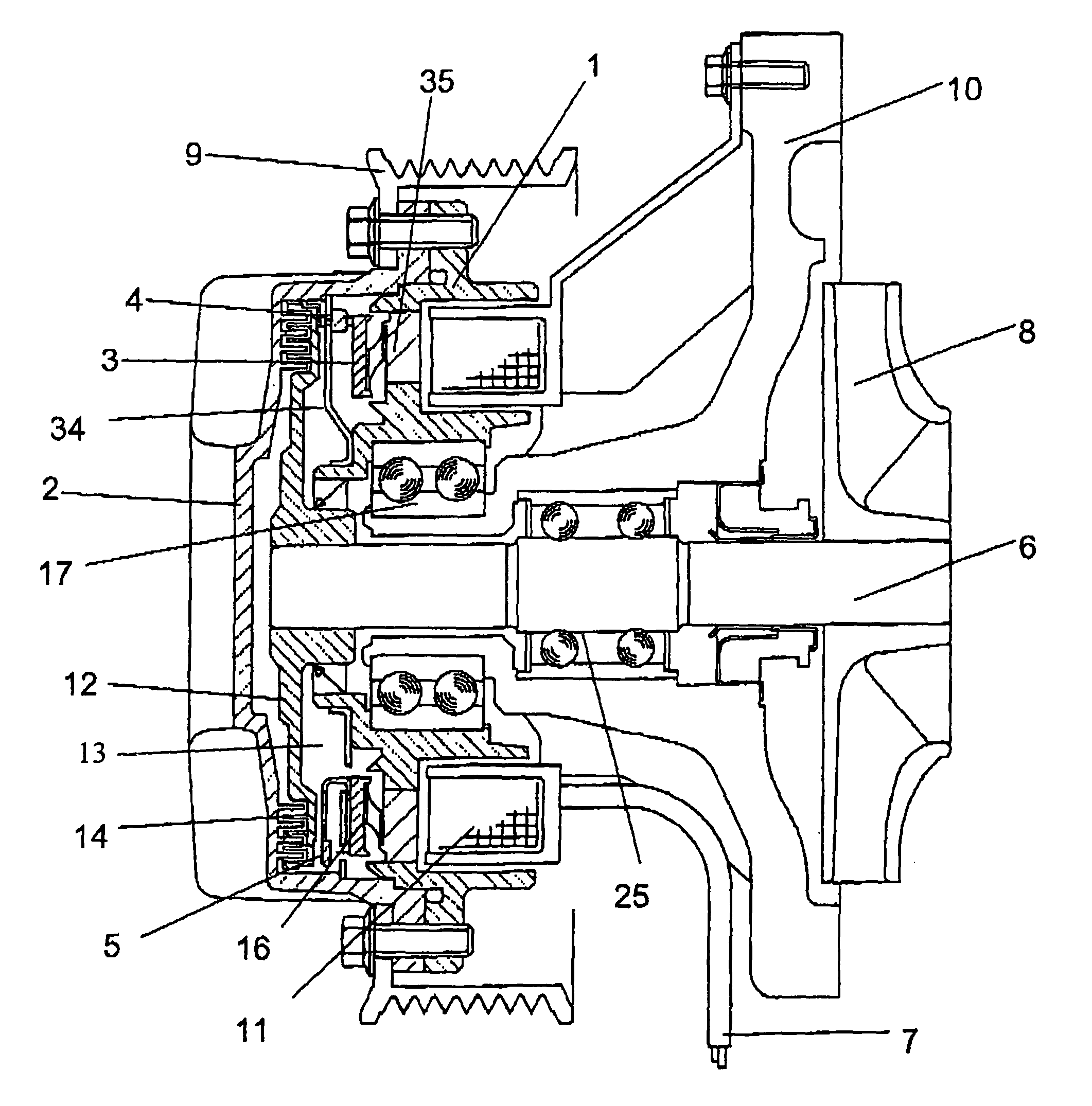
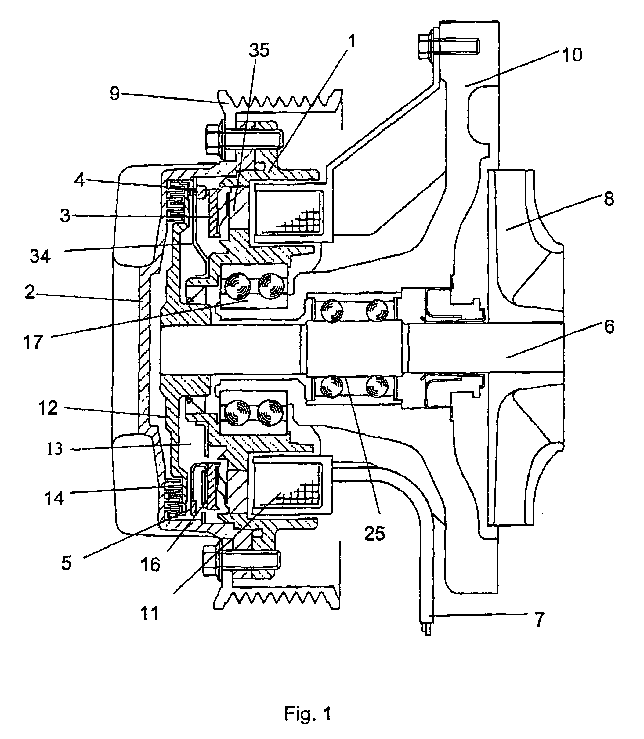
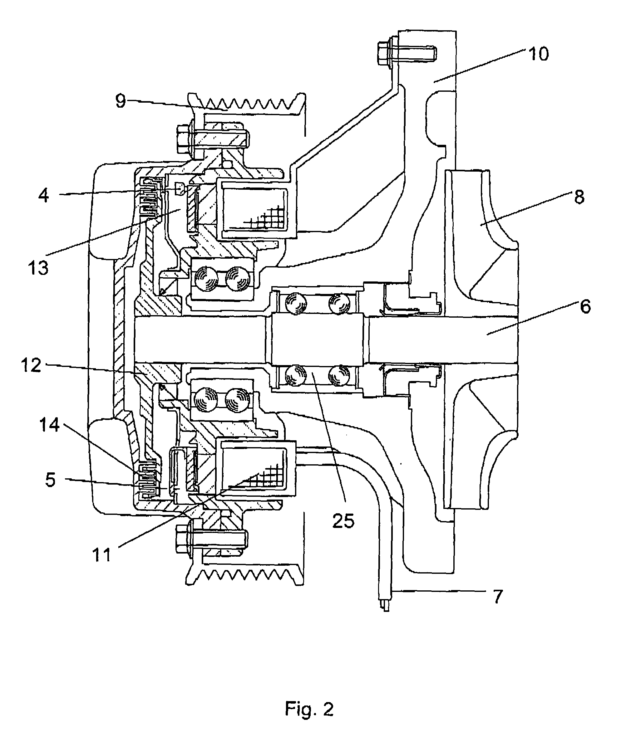
[0020]The regulatable drive according to the invention is particularly suitable for use in a motor vehicle, in particular for a water pump in a motor vehicle. It has a rotatably mounted shaft on which at least one driven member is mounted in a rotationally fixed manner and at least one drive member rotatably mounted thereon. Between the drive member and the driven member is defined a coupling region which can receive a viscous fluid. The regulatable drive comprises at least one first and at least one second flow path, which connect a fluid storage space to the coupling region between the drive member and driven member. The regulatable drive further includes a device which can be varied in its position by means of at least one actuator and which varies at least one passage orifice of at least one flow path of the drive.

[0021]The term “drive member” is understood, according to the present invention, to mean at least partially profiled disks which are mounted rotatably or fixedly in te...


PUM


Abstract

A regulatable drive for a motor vehicle, in particular for a water pump in a motor vehicle, has a rotatably mounted shaft, on which is located a rotatably mounted drive member and a rotationally fixed driven member. Between the drive member and driven member, a coupling region is defined, which can receive a viscous fluid for selectively coupling the drive member and driven member. The regulatable drive includes at least one first and at least one second flow path, which connect a fluid storage space to the coupling region, and it has a device which can be varied in its position by means of at least one actuator and which varies at least one passage orifice of at least one of the flow paths.

Description

CROSS-REFERENCE TO RELATED PATENT APPLICATIONS[0001]The right of priority under 35 U.S.C. §119(a) is claimed based on Federal Republic of Germany Patent Application 10 2004 009 073.4, filed Feb. 23, 2004, including the entire disclosure of which, including the specification, drawings, claims and abstract, is incorporated herein by reference.BACKGROUND OF THE INVENTION[0002]The present invention relates to a regulatable drive for a motor vehicle component, in particular for a water pump in a motor vehicle.[0003]Regulatable drives for use in a motor vehicle are known and serve, for example, for regulating the water pump rotational speed in order to regulate the volume flow of the cooling medium for an internal combustion engine as a function of the heat energy to be discharged. The couplings used in the prior art present the problem, inter alia, that a reliable rotational speed setting is problematic because of the difficult torque transmission or the regulating range is relatively sm...

Claims


Application Information

Patent Timeline
Patent Type & Authority Patents(United States)
IPC IPC(8): F04B49/00F04B17/00F01P5/12F01P7/04F01P7/16F16D35/02
CPCF01P5/12F16D35/024F01P7/042F01P7/162F01P7/164
Inventor BAUMGARTNER, ROLANDMAUS, RALFSCHULTHEISS, GEROLD
Owner BEHR GMBH & CO KG
Learn More