Guided transport unit

a technology of transport unit and guide rod, which is applied in the direction of vehicles, transportation and packaging, etc., can solve the problems of inability to employ moving structures, inability to provide pre-determining and precise angular orientation, and inability to use existing methods

Active Publication Date: 2010-10-26
AXIS ENERGY SERVICES LLC
View PDF7 Cites 84 Cited by
  • Summary
  • Abstract
  • Description
  • Claims
  • Application Information

AI Technical Summary

Benefits of technology

[0005]The embodiments relate generally to a guided transport unit, that includes a skid pad, a vertical displacing member engaged with the skid pad, a base operatively associated with the vertical displacing member, and a directional actuator. The base includes a planar element for engaging the surface over which the superstructure is transported, and a carrier for moving the vertical displacing member and the skid pad relative to the surface. The directional actuator controls and secures the relationship among the vertical displacing member, the base, and the skid pads for positioning the base in a predetermined direction to engage the surface, setting the carrier to move each skid pad in the predetermined direction across the planar element of the base, and then repositioning the base in another direction for movement of the guided transport unit.

Problems solved by technology

This disassembly and reassembly of the drilling rig requires an extended period of downtime and manpower, regardless of whether the next drilling site location is miles away or just a few feet from the original site.
Although manually-operated walking or moving structures are available in the industry, as disclosed in U.S. Pat. No. 5,921,336; U.S. Pat. No. 3,921,739; and U.S. Pat. No. 1,001,299, all of which are incorporated herein by reference, the manually-operated walking or moving structures do not employ a guidance system for aligning the walking substructures, changing directions in calculated angular movements, accurately and safely moving the walking rig in predetermined and precise angular movements, and maintaining, securing, and / or locking precise angular orientations.
In addition, the existing methods do not provide pre-determining and providing a uniform and precisely angular orientation and / or locking of the position of each jack pad while in movement.
The misaligning of the jack pads can cause unwanted force on the structure and can cause damage to both the transport unit and the drilling rig that it is carrying.

Method used


Image

  • Guided transport unit
  • Guided transport unit
  • Guided transport unit

Examples


Embodiment Construction

[0017]For a further understanding of the nature and objects of the present invention, reference should be made to the following detailed description, taken in conjunction with the accompanying drawings. However, before explaining the present embodiments in detail, it is to be understood that the embodiments are not limited to the particular descriptions and that the embodiments can be practiced or carried out in various ways.

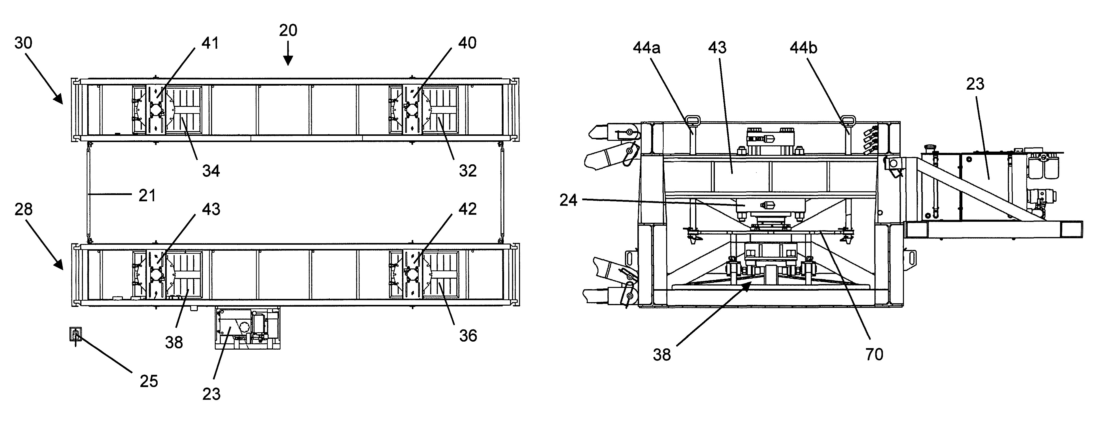
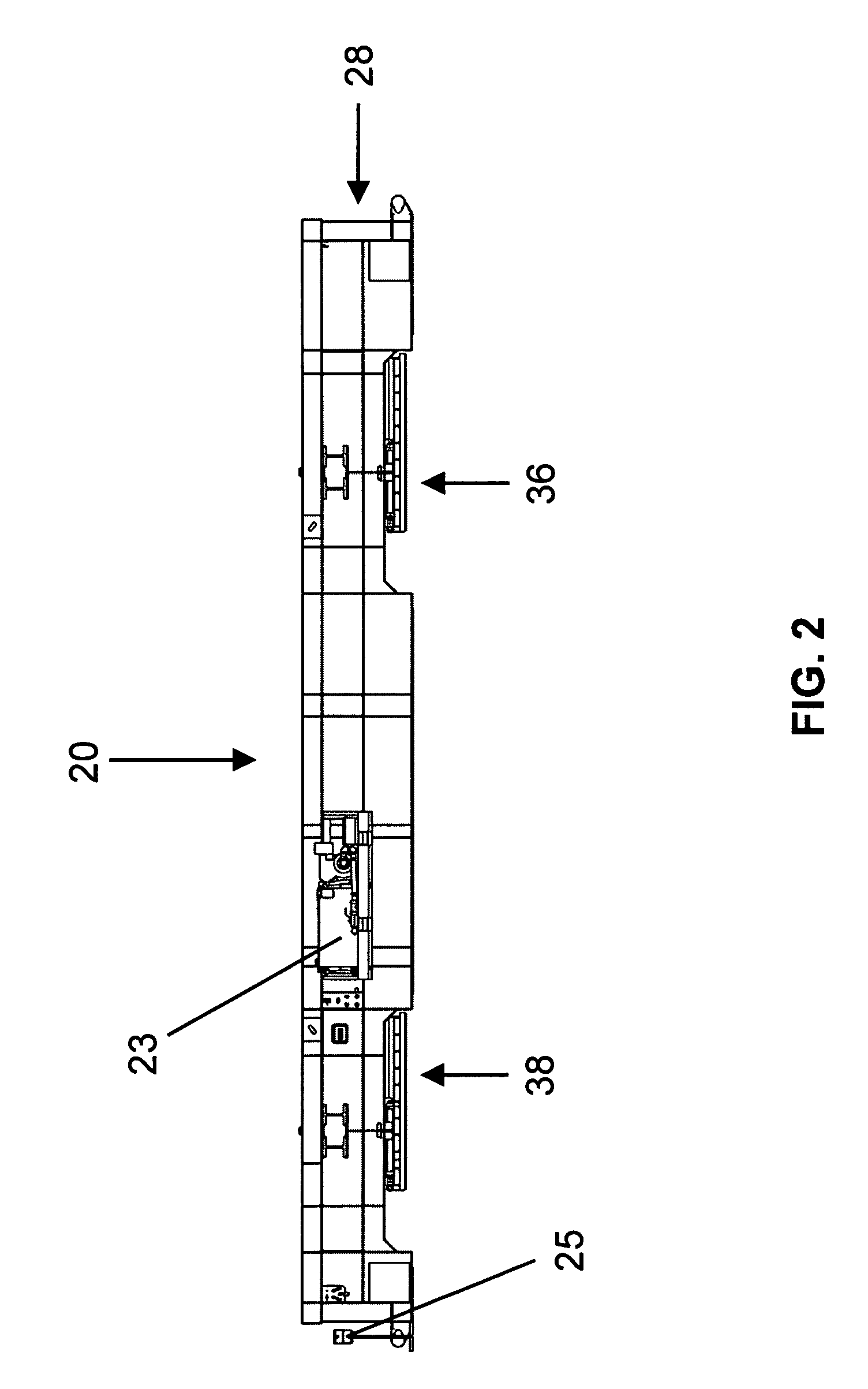
[0018]The embodiments of the apparatus and methods relate generally to a guided transport unit for moving superstructures or heavy equipment over a surface, such as a drilling rig, and include using a directional actuator or guidance system for predetermining angular settings to create precise angular movements of the guided transport unit and to secure desired angular positions and / or orientations of the guided transport unit.

[0019]Benefits of the present invention include precise angular movements of the guided transport unit for moving and transporting supers...


PUM


Abstract

A guided transport unit and methods of guiding the transport unit for moving a superstructure in precise angular movements over a surface are disclosed. The guided transport unit comprises a skid pad, a vertical displacing member engaged with the skid pad, a base operatively associated with the vertical displacing member, and a directional actuator. The base includes a planar element for engaging the surface over which the superstructure is transported, and a carrier for moving the vertical displacing member and skid pad relative to the surface. The directional actuator controls and secures the relationship among the vertical displacing member, the base, and the skid pad for positioning the base in a predetermined direction to engage the surface, setting the carrier to move each skid pad in a predetermined direction across the planar element of the base, and repositioning the base in another direction for movement of the guided transport unit.

Description

TECHNICAL FIELD[0001]The embodiments of the apparatus and methods relate generally to a guided transport unit for moving superstructures over a surface and including a directional actuator for predetermining angular settings to create and secure precise angular movements of the guided transport unit.BRIEF BACKGROUND[0002]In the operation of drilling multiple wells, it is not uncommon to disassemble a drilling rig so that it can be relocated to another drilling site. This disassembly and reassembly of the drilling rig requires an extended period of downtime and manpower, regardless of whether the next drilling site location is miles away or just a few feet from the original site. Furthermore, like any business operation, ability to minimize downtime and expenses and to increase production and profits are always desired.[0003]Although manually-operated walking or moving structures are available in the industry, as disclosed in U.S. Pat. No. 5,921,336; U.S. Pat. No. 3,921,739; and U.S....

Claims


Application Information

Patent Timeline
Patent Type & Authority Patents(United States)
IPC IPC(8): B62D51/06
CPCB62D57/02
Inventor BEZNER, WILLIAM A.
Owner AXIS ENERGY SERVICES LLC
Why Eureka
Try Eureka