
Motion controlling hinge for orthopedic brace

a technology of hinges and hinges, applied in the field of orthopedic bracing, can solve the problems of degenerative changes within the joint, injury to other structures, and people often having difficulty avoiding small flexion angles during normal activities

Active Publication Date: 2010-10-12
DJO
View PDF42 Cites 30 Cited by
  • Summary
  • Abstract
  • Description
  • Claims
  • Application Information

AI Technical Summary

Benefits of technology

The patent describes a hinge used for orthopedic braces that allows for controlled motion. The hinge has a specific design and process for making and using it, but it can also be modified in various ways without affecting its main function. The hinge is not limited to the specific embodiments discussed and covers all modifications within its scope. The technical effect of this patent is to provide a versatile hinge for orthopedic braces that allows for controlled motion while being adaptable to various needs and modifications.

Problems solved by technology

For patients who have recently undergone ACL reconstruction, this strain can cause permanent stretching of the ACL graft, which can in turn create knee instability that could lead to injury of other structures (e.g. meniscus), or to degenerative changes within the joint.
However, people often have difficulty avoiding small flexion angles during normal activities.
A patient wearing such a brace experiences a jarring at maximum extension as the brace comes to a sudden halt.
Many patients may find this jarring uncomfortable, and the jarring may cause many patients to fail to comply with the rehabilitation guidelines set by their physicians.
Such jarring impacts frequently cause injuries.
The assemblage thus decelerates the limb during the last 15 to 20 degrees of extension, preventing the arms from striking a stop, which would create a risk of hyperextension.
None of these braces provides the ability to adjust a magnitude of a force that restrains hinge motion without the necessity of interchanging hinge parts.
Further none of these braces provides the advantageous combination of easy adjustability of a magnitude of a force that restrains hinge motion, easy adjustability of an angle at which the hinge motion controlling force is applied, and the capability to turn off the hinge motion controlling force when desired.

Method used


Image

  • Motion controlling hinge for orthopedic brace
  • Motion controlling hinge for orthopedic brace
  • Motion controlling hinge for orthopedic brace

Examples


Embodiment Construction

,” one will understand how the features of the preferred embodiments provide advantages, which include easy adjustability of a magnitude of a force that restrains hinge motion, easy adjustability of an angle at which the hinge motion controlling force is applied, and the capability to turn off an extension resistance provided by the hinge.

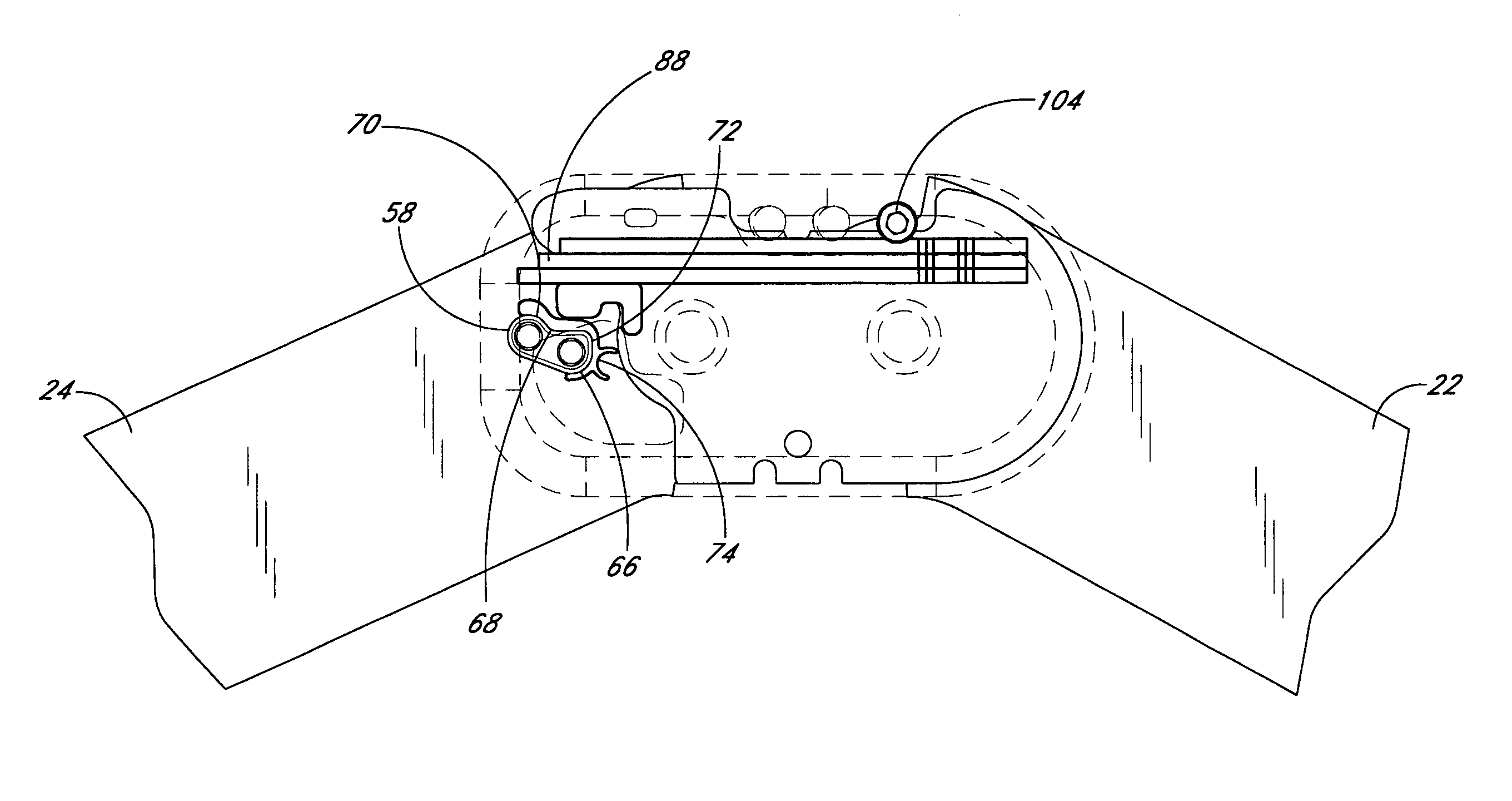
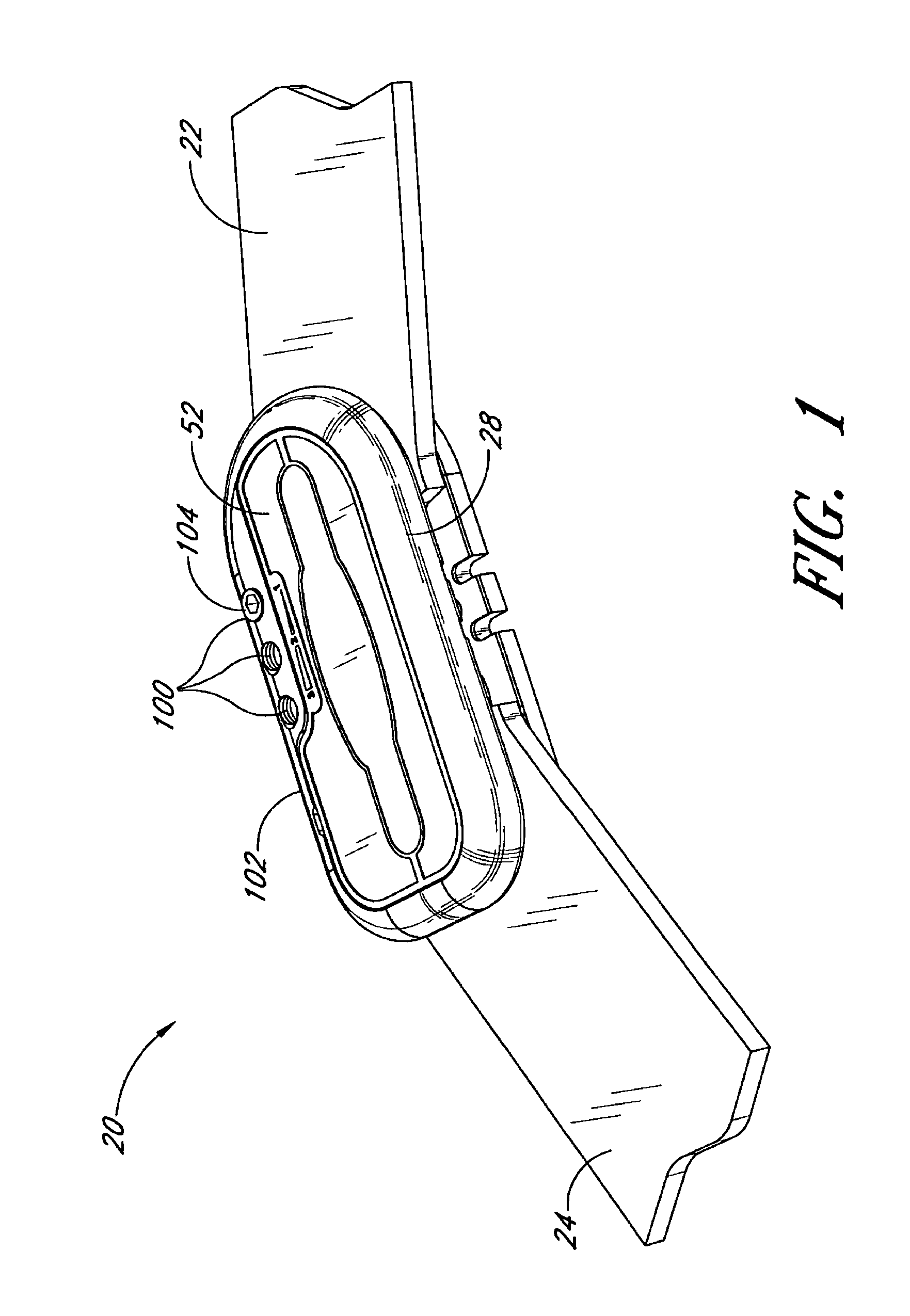
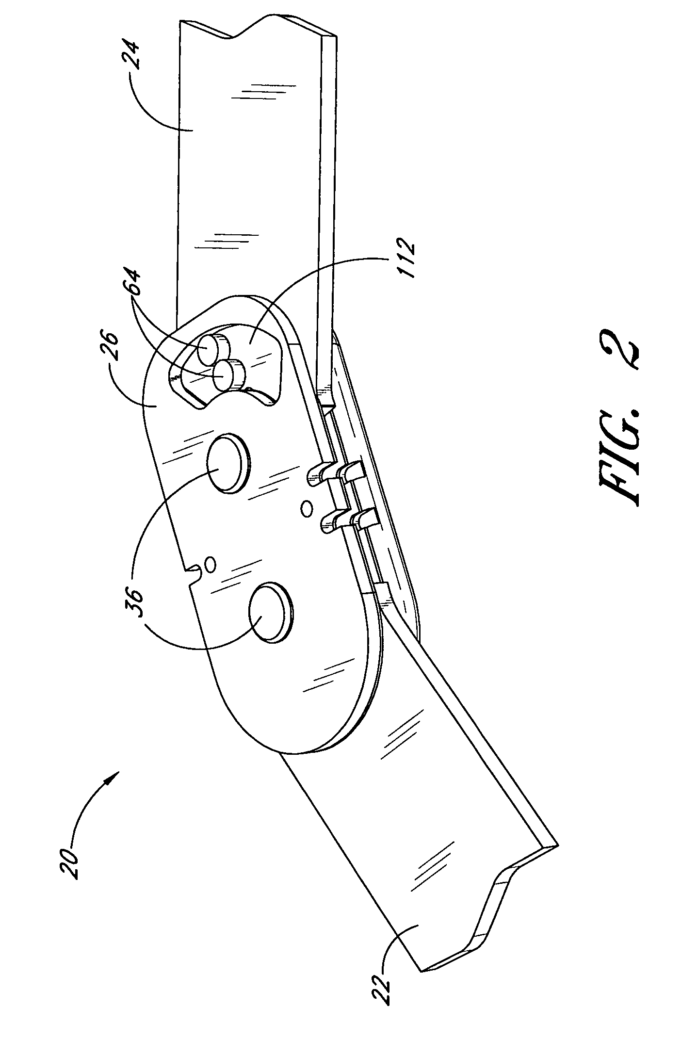
[0015]One embodiment of the hinge for orthopedic brace comprises a hinge plate, a spring member, and first and second arms pivotably secured to the hinge plate. An actuator is secured to the second arm. As the arms pivot in a first direction such that an angle between them increases, once the arms reach a desired extension angle, the spring member exerts a force on the actuator tending to bias the second arm in a second direction opposite the first direction. This embodiment may further comprise a cam pivotably secured to the hinge. The cam is pivotable between an “ON” position and an “OFF” position. The spring member biases the second arm only whe...


PUM


Abstract

A motion controlling hinge for an orthopedic brace is provided. The hinge includes an actuator secured to one arm, and at least one spring member. As the arm with the actuator pivots in a first direction, at a predetermined flexion angle the actuator applies a force to the spring member, causing the spring member to flex. The spring member exerts a force on the actuator tending to bias the actuator away from the spring member, and tending to bias the arm in a second direction opposite the first direction. In one embodiment, the spring member comprises a plurality of flat bar leaf springs. A movable fulcrum enables adjustment of a force exerted by the spring member on the actuator. A variety of differently sized adapters are securable to the actuator. The size of the adapter determines the flexion angle at which the spring member first exerts force on the actuator. In some embodiments, the hinge includes an “ON” / “OFF” switch that enables a user to disengage biasing force provided by the spring member. When the switch occupies the “OFF” position, the hinge is freely pivotable to a maximum extension angle.

Description

RELATED APPLICATION[0001]This application claims priority to provisional application Ser. No. 60 / 583,252, filed on Jun. 24, 2004, the entire contents of which are hereby expressly incorporated by reference.BACKGROUND OF THE INVENTION[0002]1. Field of the Invention[0003]The present invention relates to orthopedic bracing.[0004]2. Description of the Related Art[0005]The quadriceps muscles serve as an anterior cruciate ligament (ACL) antagonist that strain the ACL, particularly at smaller knee flexion angles. At knee flexion angles less than 60°, a component of the quadriceps force acts in the anterior direction. Knee structures, primarily the ACL, resist this anterior component. Thus, quadriceps contractions at small flexion angles place strain on the ACL. This strain may be responsible for many ACL injuries. For patients who have recently undergone ACL reconstruction, this strain can cause permanent stretching of the ACL graft, which can in turn create knee instability that could lea...

Claims


Application Information

Patent Timeline
Patent Type & Authority Patents(United States)
IPC IPC(8): A61F5/00A61F5/37A61B19/00
CPCA61F5/0123A61F2005/0137A61F2005/0139A61F2005/0167A61F2005/0179
Inventor SELIGMAN, SCOTT
Owner DJO
Learn More