
Double-walled stent system

a stent system and double-walled technology, applied in the field of intraluminal stents, can solve the problems of leaking backward across, restricted blood flow, and valve proper functioning,

Active Publication Date: 2010-10-05
MEDTRONIC VASCULAR INC
View PDF13 Cites 267 Cited by
  • Summary
  • Abstract
  • Description
  • Claims
  • Application Information

AI Technical Summary

Benefits of technology

The double-walled stent system minimizes the need for repeated surgeries by accommodating patient growth and vessel irregularities, ensuring consistent blood flow and proper valve placement, thereby reducing surgical burdens and improving patient outcomes.

Problems solved by technology

Heart valves, such as the mitral, tricuspid, aortic and pulmonary valves, are sometimes damaged by disease or by aging, resulting in problems with the proper functioning of the valve.
Heart valve problems generally take one of two forms: stenosis, in which a valve does not open completely or the opening is too small, resulting in restricted blood flow; or insufficiency, in which blood leaks backward across a valve when it should be closed.
Over time, the right ventricle enlarges, which leads to congestive heart failure (CHF).
In severe cases, the CHF results in clinical symptoms including shortness of breath, fatigue, chest pain, fainting, heart murmur, and in babies, poor weight gain.
Previously, valve repair or replacement required open-heart surgery with its attendant risks, expense, and extended recovery time.
Open-heart surgery also requires cardiopulmonary bypass with risk of thrombosis, stroke, and infarction.
However, as the child grows, the valve can become too small to accommodate the blood flow to the lungs that is needed to meet the increasing energy demands of the growing child, and it may then need to be replaced with a larger valve.
Alternatively, in a patient of any age, the implanted valve may fail to function properly over time due to calcium buildup and have to be replaced.
These surgical replacement procedures are physically and emotionally taxing, and a number of patients choose to forgo further procedures after they are old enough to make their own medical decisions.

Method used


Image

  • Double-walled stent system
  • Double-walled stent system
  • Double-walled stent system

Examples


Embodiment Construction

[0057]Specific embodiments of the present invention are now described with reference to the figures, wherein like reference numbers indicate identical or functionally similar elements. The terms “distal” and “proximal” are used in the following description with respect to a position or direction relative to the treating clinician. “Distal” or “distally” are a position distant from or in a direction away from the clinician. “Proximal” and “proximally” are a position near or in a direction toward the clinician.

[0058]The following detailed description is merely exemplary in nature and is not intended to limit the invention or the application and uses of the invention. Although the description of the invention is in the context of treatment of blood vessels such as the coronary, carotid and renal arteries, the invention may also be used in any other body passageways where it is deemed useful. Furthermore, there is no intention to be bound by any expressed or implied theory presented in ...


PUM


Abstract

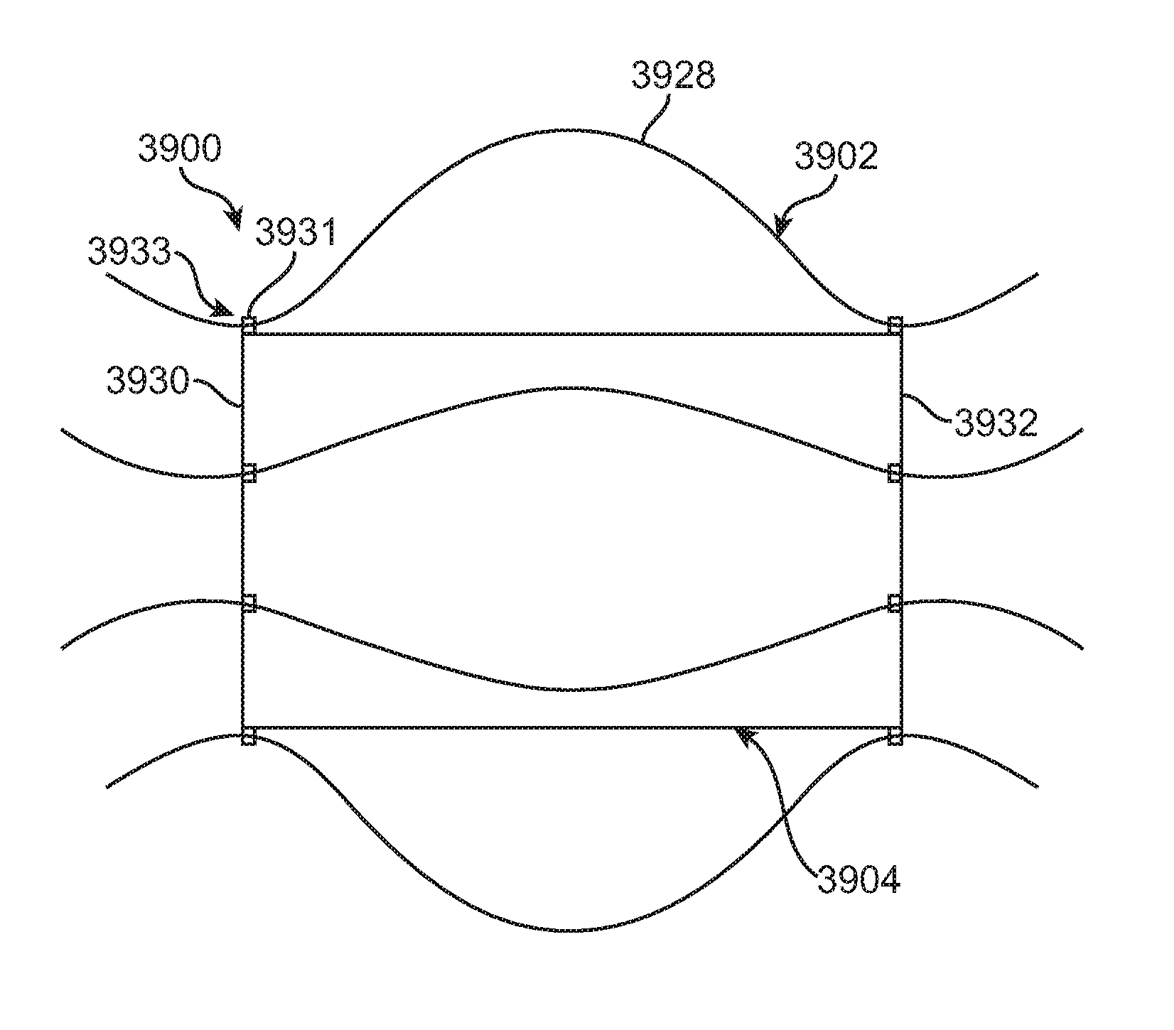
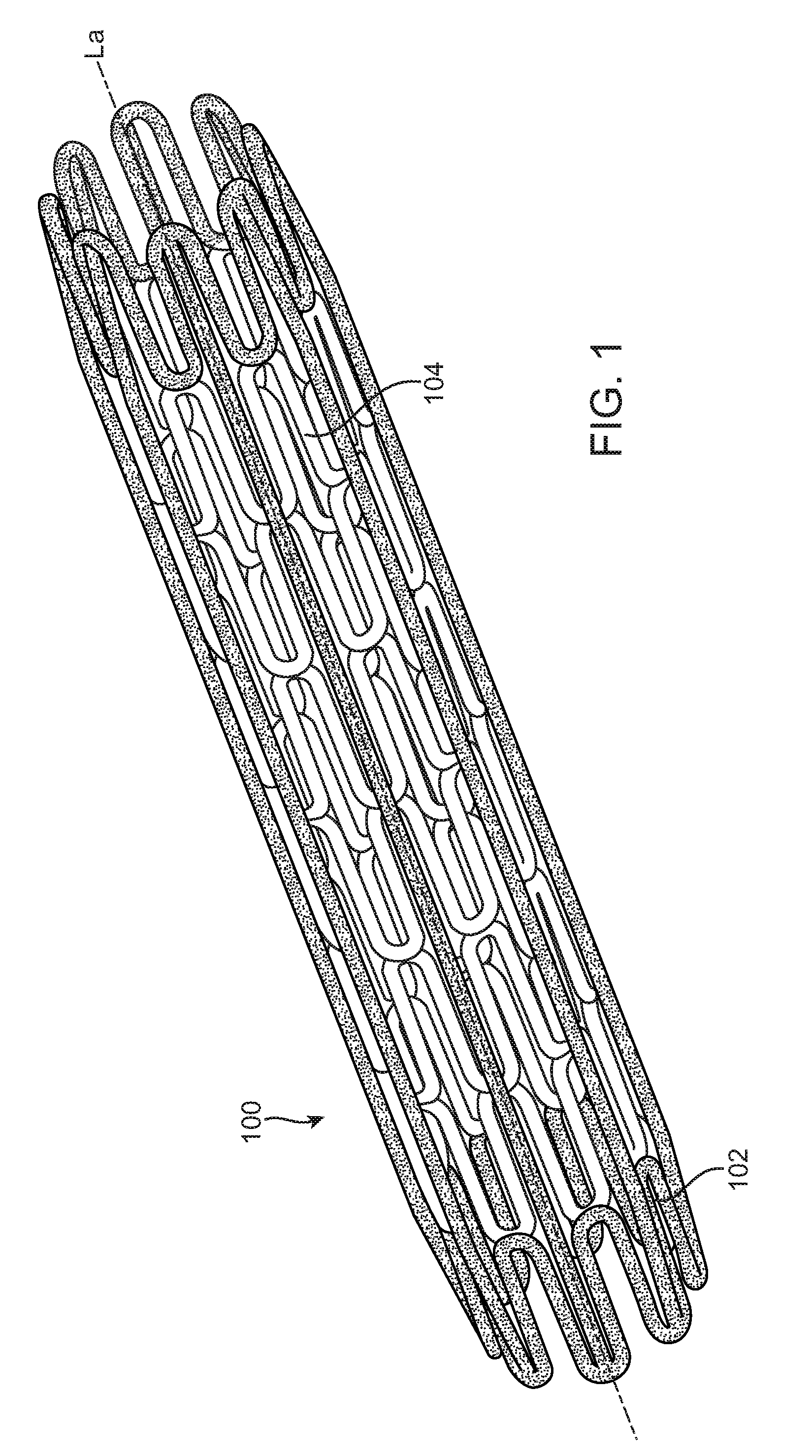
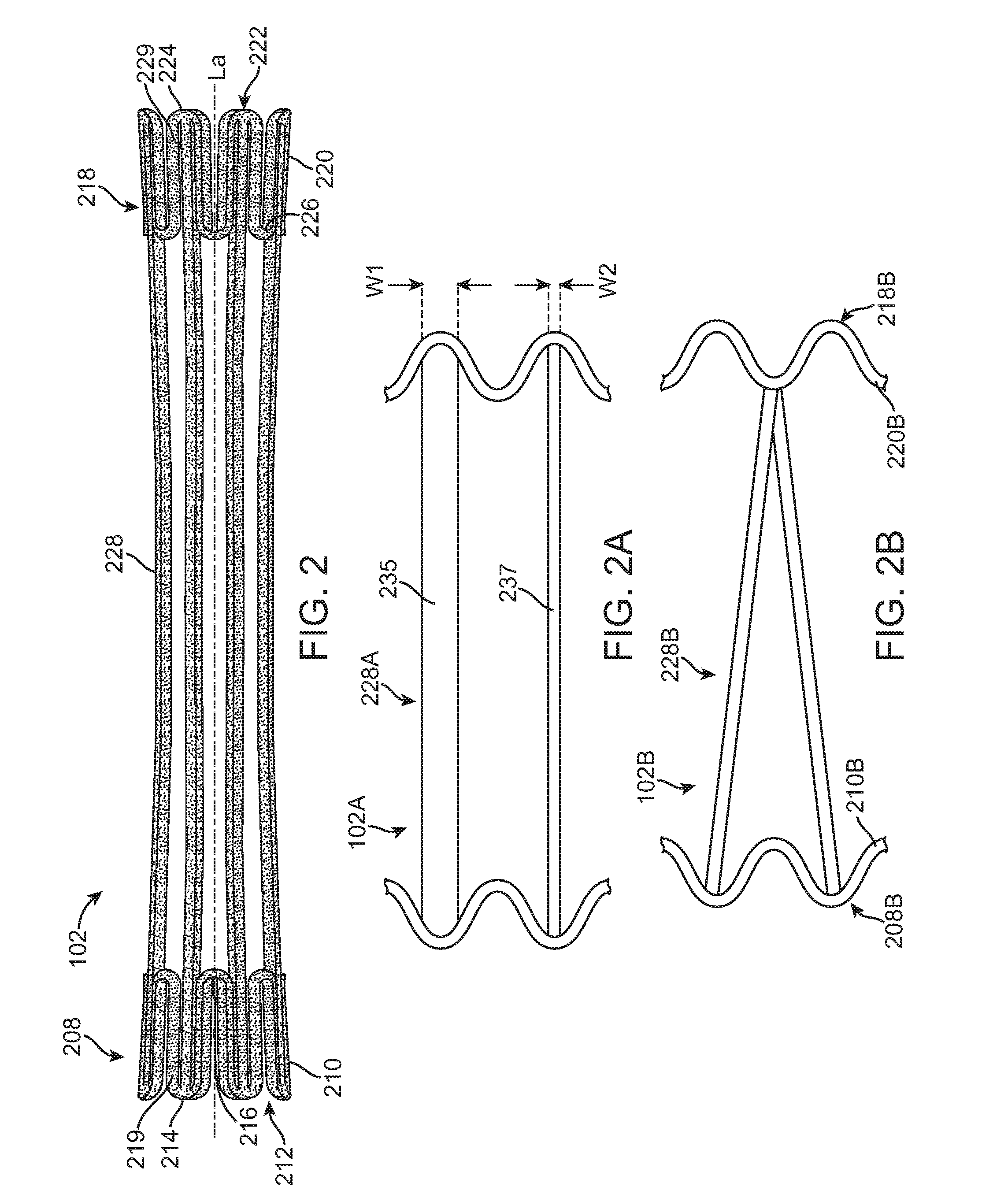
A double walled stent system particularly suited for treating abnormalities of the right ventricular outflow tract is disclosed having an exterior stent component and an interior stent component. The exterior stent component is secured to the interior stent component in a non-fixed, sliding relationship. The exterior stent component includes a plurality of longitudinally-extending connectors such as straight or sinusoidal bands. The interior stent component has a generally tubular cylindrical body and is centered within the exterior stent component. The stent system has a contracted delivery configuration and a radially expanded configuration for contacting the vessel wall. When deployed, the longitudinally-extending connectors of the exterior stent component come in contact with the vessel wall and fix the stent system to the treatment site. The interior stent component also radially expands but remains centered inside the exterior component and makes little to no contact with the vessel wall.

Description

FIELD OF THE INVENTION[0001]The present invention is directed to intraluminal stents for use in a body lumen. More particularly, the present invention is directed to a double-walled stent system.BACKGROUND OF THE INVENTION[0002]Heart valves, such as the mitral, tricuspid, aortic and pulmonary valves, are sometimes damaged by disease or by aging, resulting in problems with the proper functioning of the valve. Heart valve problems generally take one of two forms: stenosis, in which a valve does not open completely or the opening is too small, resulting in restricted blood flow; or insufficiency, in which blood leaks backward across a valve when it should be closed.[0003]The pulmonary valve regulates blood flow between the right ventricle and the pulmonary artery, controlling blood flow between the heart and the lungs. Pulmonary valve stenosis is frequently due to a narrowing of the pulmonary valve or the pulmonary artery distal to the valve. This narrowing causes the right side of the...

Claims


Application Information

Patent Timeline
Patent Type & Authority Patents(United States)
IPC IPC(8): A61F2/06A61F2/86A61F2/82
CPCA61F2/2418A61F2/91A61F2/915A61F2/852A61F2230/0076A61F2002/823A61F2002/825A61F2002/828A61F2002/91558A61F2002/91591A61F2250/0037A61F2250/0063A61F2250/0082A61F2220/0058A61F2230/0013A61F2230/0054A61F2230/0071
Inventor BLOOM, ELIOTRAFIEE, NASSERHOUSE, MORGAN
Owner MEDTRONIC VASCULAR INC
Learn More