
Aerodynamic properties of ground vehicles

a technology of aerodynamic properties and ground vehicles, applied in the direction of vehicle bodies, influencers using rotating members, monocoque constructions, etc., can solve the problems of large wake region, large drag force, unsteady airflow, etc., to reduce the amount of soiling of the vehicle's exterior surface, improve the efficiency of the airflow control system, and reduce the effect of air vortex

Inactive Publication Date: 2010-09-14
SEMCON CARAN
View PDF47 Cites 16 Cited by
  • Summary
  • Abstract
  • Description
  • Claims
  • Application Information

AI Technical Summary

Benefits of technology

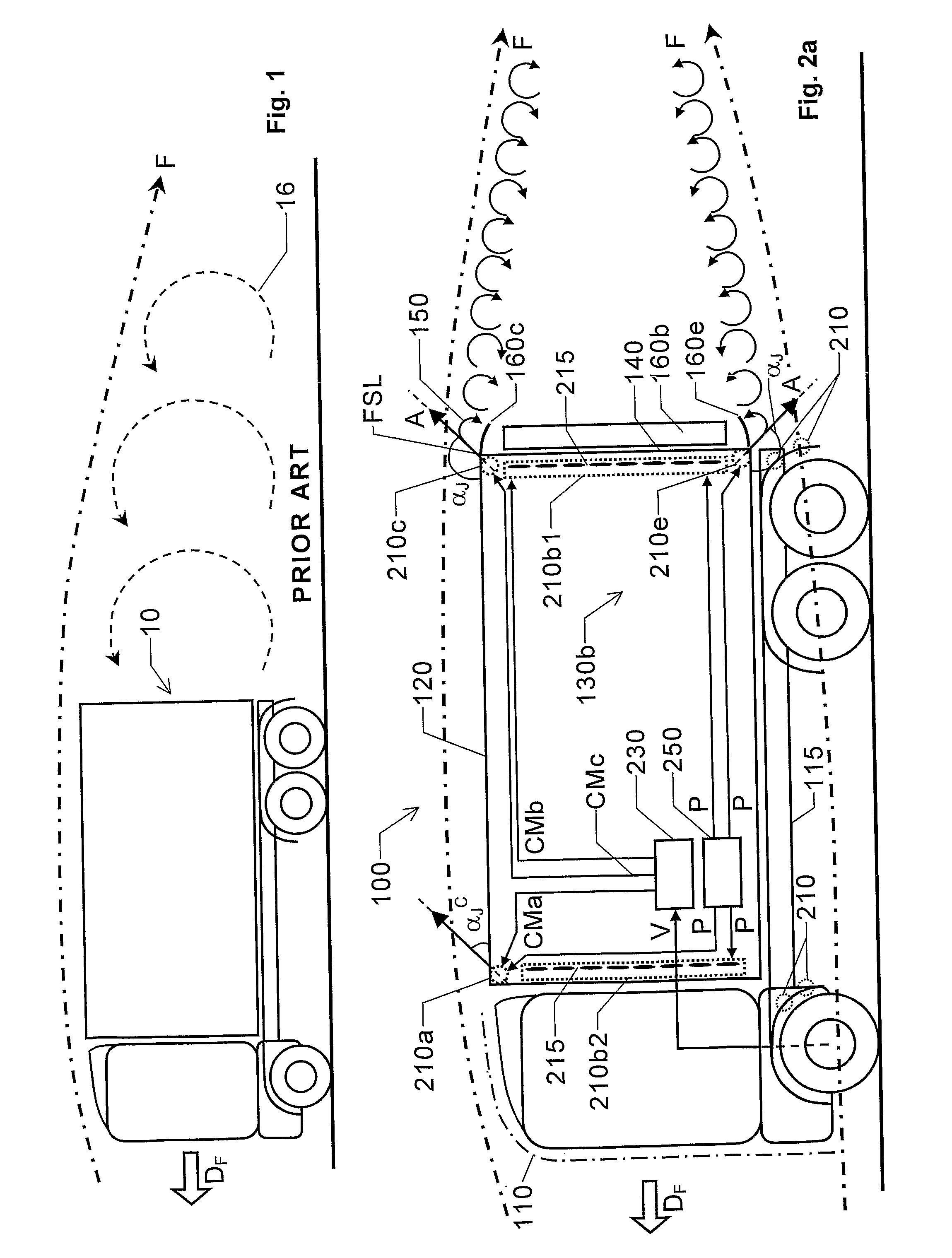
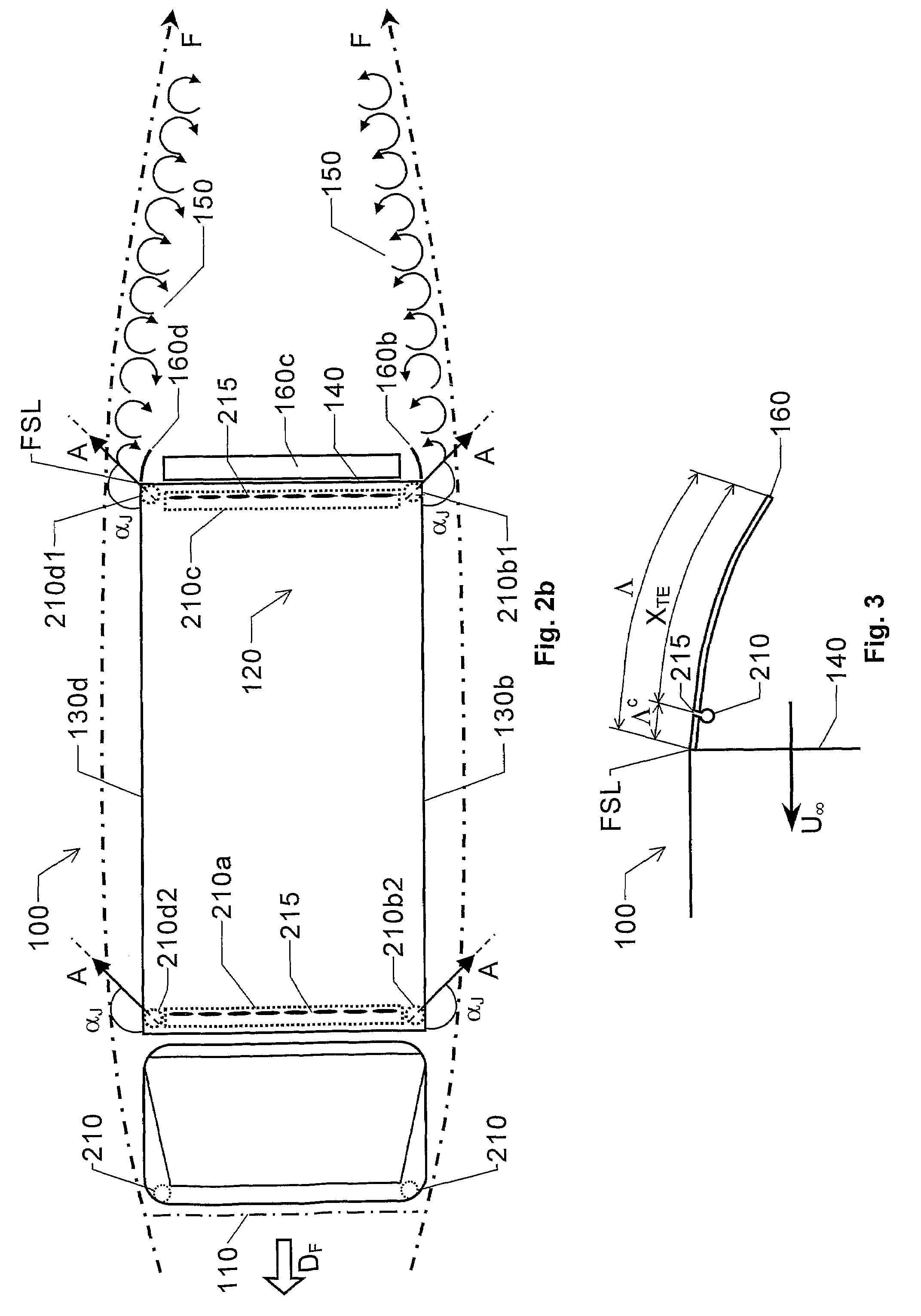
"The present invention provides an airflow control system for ground vehicles that reduces air resistance, improves stability, and reduces the likelihood of undesired lift forces. The system includes an air modulator with an array of openings that create oscillating air vortices outside the vehicle, which in turn reduces global vortices behind the vehicle. The openings have a specific orientation relative to the vehicle's speed, which further enhances the system's effectiveness. The air modulator can be controlled to output oscillating air from each opening at a desired frequency, and the system can be easily integrated into existing vehicle designs."

Problems solved by technology

This results in a high drag force and a large wake region.
The airflow often exhibits unsteadiness in the form of periodic vortex formation and shedding.
Naturally, these effects are undesired.
However, for ground vehicles (trucks, busses and trailers in particular) various regulations place restrictions on the vehicles' maximum outer dimensions.
Blowers emit air through openings in the rear wall of the vehicle to increase the Bernoulli's total pressure behind the vehicle, and thus reduce the air resistance.
However, the known strategies either fail to reduce the air drag behind large vehicles sufficiently, and / or these strategies imply an apparatus that is complex, expensive and / or unreliable.

Method used


Image

  • Aerodynamic properties of ground vehicles
  • Aerodynamic properties of ground vehicles
  • Aerodynamic properties of ground vehicles

Examples


first embodiment

[0065]FIG. 5a shows section of a proposed air modulator 210 according to the invention. The air modulator 210 has a tubular element on which an array of openings is arranged. In the illustrated section of the air modulator 210 one exemplifying opening in the form of a slot 515 is included. This slot 515 has a width dimension W and a length L dimension, where the length dimension L is several factors larger than the width dimension W. Preferably, the width dimension W lies in a range from approximately 0.1 mm to approximately 10 mm (more preferably, 0.3 mm

[0066]The tubular element includes a modulating member 520 that extends along a substantial portion of an interior of the tubular element. The modulating member 520 has a polygon shaped cross section, such a hexagon or a pentagon. However, any other regular or irregular cross section shape is conceivable according to the invention...

second embodiment

[0069]FIG. 6a shows a section of a proposed air modulator 210 according to the invention. Here, the air modulator 210 includes at least one diaphragm 620, which is arranged in a cavity 625 adjoining at least one opening in the above-mentioned array of openings. Preferably, corresponding cavities and diaphragms are arranged behind each opening (here in the form of slots 615) in the air modulator's 210 array of openings.

[0070]Nevertheless, in case the openings are slots, each slot 615 has a width dimension W and a length L dimension, where the length dimension L is several factors larger than the width dimension W. Preferably, the width dimension W lies in a range from approximately 0.1 mm to approximately 10 mm (more preferably 0.3-2.0 mm), and the length dimension L lies in a range from approximately 30 mm to approximately 300 mm. Moreover, as can be seen in the FIG. 6a, all the slots 615 in the array of openings are positioned next to one another along an essentially straight line ...

third embodiment

[0075]FIG. 7a shows a section of the air modulator 210 according to the invention, wherein an array of openings 215 contains a number of openings 715 arranged next to one another along an essentially straight line 630. Here, the air modulator 210 is represented by a set of valves 710, 720, 730 and 740 respectively. Namely, each opening 715 is connected to an air conduit, which is further connected to one of the valves 710, 720, 730 and 740. Each of these valves, in turn, 710, 720, 730 and 740 is connected to a compressed air system 250 via one or more further air conduits, so that an active airflow P can be received. Each valve 710, 720, 730 and 740 is controllable by a control unit 230 in response to a control signal CM. Thereby, the openings 715 may be controlled to emit synthetic air vortices according to what has been described above.

[0076]FIG. 7b shows a section of the air modulator 210 according to the third embodiment of the invention, however, where a sub-set of openings 615...


PUM


Abstract

The present invention relates to the improvement of the aerodynamic properties of bluff-body shaped ground vehicles. A least one air modulator is assembled on the vehicle to modify an air flow around the vehicle, such that the drag on the vehicle is decreased. Each air modulator has an array of openings including a number of openings, which are arranged next to one another along an essentially straight line. A control unit controls the at least one air modulator output oscillating air from each opening such that air vortices are formed outside the opening. The at least one air modulator is arranged on the vehicle, such that these air vortices have axes that, in proximity to the opening, are essentially perpendicular to a forward driving direction of the vehicle.

Description

THE BACKGROUND OF THE INVENTION AND PRIOR ART[0001]The present invention relates generally to the improvement of the aerodynamic properties of vehicles, such as trucks, busses, trains, trailers, passenger cars, hovercrafts and motorcycles. More particularly, the invention relates to an airflow control system for ground vehicles, such as bluff-body shaped ground vehicles.[0002]Various solutions are known for improving the aerodynamic properties of a so-called bluff body, i.e. a non-streamlined shape that produces considerable resistance when moving through the air, or a similar medium. Typically, a region of separated airflow occurs over a large portion of the surface of a bluff body. This results in a high drag force and a large wake region. The airflow often exhibits unsteadiness in the form of periodic vortex formation and shedding. Naturally, these effects are undesired. Therefore, to obtain low fuel consumption, bluff-body vehicle shapes should generally be avoided. However, for...

Claims


Application Information

Patent Timeline
Patent Type & Authority Patents(United States)
IPC IPC(8): B62D35/00
CPCB62D35/00B62D37/02B62D35/001
Inventor KJELLGREN, PERFREDRIKSSON, SAM
Owner SEMCON CARAN
Learn More