
Piston actuated vapor-dispersing device

a vapor-dispersing device and piston-actuated technology, which is applied in the field of electronic vapor-dispersing devices, can solve the problems of many limitations of such devices, devices that contain pistons are extremely scant in the literature, and devices slow down, and achieve the effect of smoothing out the delivery of volatile liquid over tim

Inactive Publication Date: 2010-09-14
HENKEL KGAA
View PDF22 Cites 46 Cited by
  • Summary
  • Abstract
  • Description
  • Claims
  • Application Information

AI Technical Summary

Benefits of technology

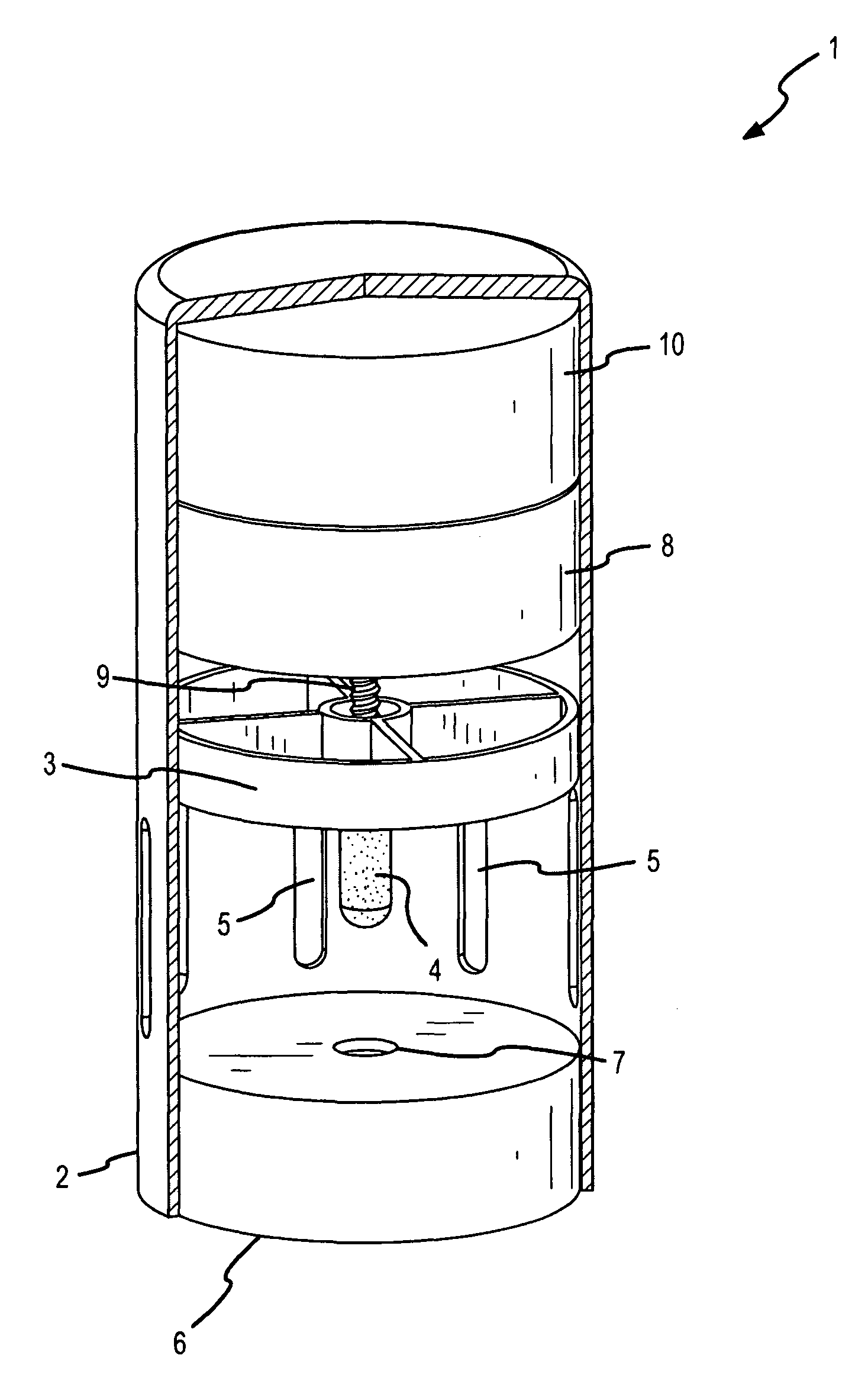
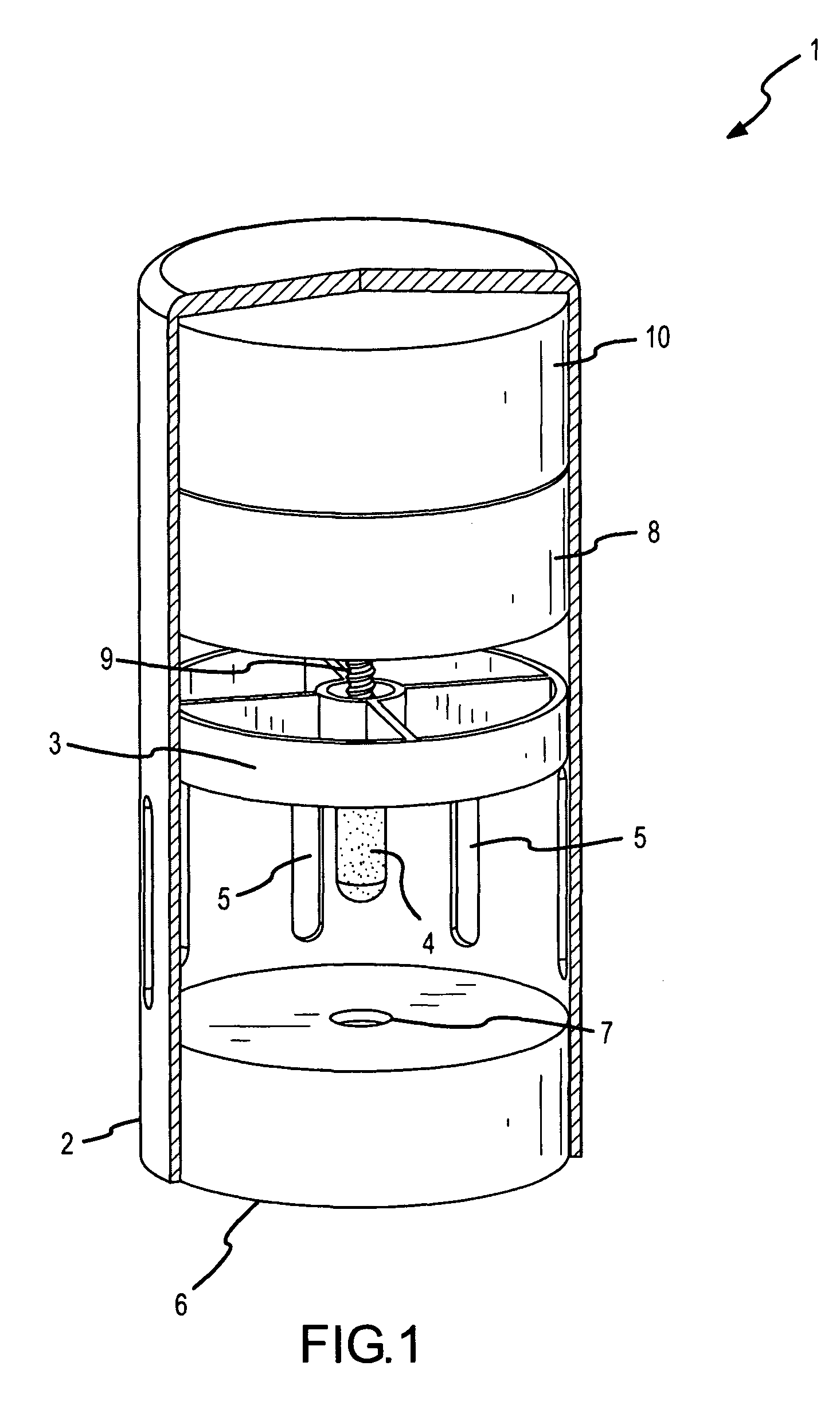
The present invention is a device that can smoothly deliver a volatile liquid over time by moving a porous member in a piston. This device includes a housing with a vent for air exchange, a movable piston with an attached porous member, a reservoir with a breachable opening containing the volatile liquid, an electromechanical means to move the piston, a drive means connecting the piston with the electromechanical means, and an electrical means to power and control the electromechanical means and hence the piston. The invention also provides a previously unheard of method for evaporating a liquid that involves repetitive dipping of a porous member into a volatile liquid.

Problems solved by technology

In spite of the fact that fan, heater and piezoelectric air fresheners have dominated the marketplace over the last decade or so, there remain many limitations to such devices.
Most problems relate to the fact that the wick remains in constant communication with the volatile liquid, and remaining continually saturated there is separation of fragrance components through what is nothing more than column chromatography.
Invariably these devices slow down since the porous wicks clog with the less volatile ingredients and the spectrum of fragrance notes changes throughout the lifetime of the device.
Vapor-dispersing devices that contain pistons are extremely scant in the literature and are all based on movement of a piston to increase internal pressure within a reservoir to push liquid out.
None of these devices employ a moveable piston in a non-pressurized device for effecting the repeated dipping of a porous member into a volatile liquid so that the liquid is evaporated into the environment in a controlled manner.

Method used


Image

  • Piston actuated vapor-dispersing device
  • Piston actuated vapor-dispersing device
  • Piston actuated vapor-dispersing device

Examples


Embodiment Construction

[0021]The following description is of exemplary embodiments only and is not intended to limit the scope, applicability or configuration of the invention in any way. Rather, the following description provides a convenient illustration for implementing exemplary embodiments of the invention. Various changes to the described embodiments may be made in the function, the size, and arrangement of the elements described without departing from the scope of the invention as set forth in the appended claims. Most importantly, changes in shape and size of the overall device do not depart from the intended scope of the invention.

[0022]That said, the present invention relates to a piston-actuated electromechanical vapor-dispersing device that shows a more linear evaporation of volatile liquid than conventional electrical devices utilizing heater and / or fan elements.

[0023]The present invention relates to a device that minimally comprises a housing with an air vent, a movable piston with an attach...


PUM

PropertyMeasurementUnit
heightaaaaaaaaaa
diameteraaaaaaaaaa
heightaaaaaaaaaa

Abstract

A vapor-dispersing device comprising a moveable piston with a porous protuberance is described that operates by the repetitive movement of the piston to intermittently dip the porous member into a volatile liquid and to expel air out through vents.

Description

FIELD OF INVENTION[0001]The present invention relates to electromechanical vapor-dispersing devices and in particular to a vapor-dispersing device with a moveable piston that repeatedly dips a porous member into a volatile liquid to draw up the liquid from a reservoir and to move the air around the porous member creating a bellows effect that evaporates the volatile liquid from the device into the adjacent environment in a linear and controlled manner.BACKGROUND[0002]Vapor-dispersing devices are well known and include a variety of devices for vaporizing a liquid such as a perfume or insecticide into the surrounding environment. For example, vapor-dispersing devices include electrical devices with resistive heater modules and / or fans for driving liquids into the vapor phase, passive devices that rely on pads or wicks with large surface area for evaporating liquids without energy input, and simple aerosol sprays that propel and disperse liquids into fine droplets that evaporate in the...

Claims


Application Information

Patent Timeline
Patent Type & Authority Patents(United States)
IPC IPC(8): A24F25/00B67D7/00B65B53/00A61L9/04B67D7/08B05B1/08B05B9/00A62C13/62B65D69/00B65D85/00B67B7/00B67D99/00
CPCA01M1/2044A61L9/042A61L9/127A61L9/044Y10T428/21Y10T428/1328
Inventor BANKERS, JEFFREYHAFER, KEVIN
Owner HENKEL KGAA
Learn More