
Cleaning device, inkjet printer, and an inkjet printer cleaning method

a cleaning device and inkjet printer technology, applied in printing and other directions, can solve the problems of printing defects, drop dots, and inability to completely prevent the viscosity increase of ink in the nozzle from increasing, and achieve the effect of suppressing ink was

Inactive Publication Date: 2010-08-17
SEIKO EPSON CORP
View PDF18 Cites 3 Cited by
  • Summary
  • Abstract
  • Description
  • Claims
  • Application Information

AI Technical Summary

Benefits of technology

The present invention relates to a cleaning device for inkjet printers that reduces ink waste by avoiding unnecessary vacuum discharge processes in print head cleaning operations. The cleaning device includes a cleaning mechanism for cleaning the print head, a drive control unit for operating the cleaning mechanism at different process levels based on the amount of ink consumed, a counter for counting the time passed in a no-printing state, and a process selection unit for selecting between a first process level that consumes low ink and a second process level that consumes less ink than the first level. The cleaning device can also include a reporting unit for indicating that the cleaning process is unnecessary or the cleaning command was erroneously asserted. The invention aims to reduce ink waste and the cost of printing, as well as to increase the service life of the ink suction pump and other cleaning parts.

Problems solved by technology

As a result, the nozzles clog, ink is not discharged or is not discharged at the normal size and speed, resulting in printing defects (referred to below as dropped dots).
However, simply covering the print head with a cap will not completely prevent the ink in the nozzles from increasing in viscosity when nothing is printed for an extended period of time.
Depending on how the print head is used, dropped dots may also result from the ink meniscus inside the nozzles breaking during printing, such as when printing continues uninterrupted for a long time and the print head is repeatedly driven bidirectionally.
The vacuum process consumes a large amount of ink, and if the vacuum process is executed frequently by the automatic cleaning process, ink consumption rises accordingly and the cost of printing therefore rises.
Many operators of inkjet printers that have a cleaning button and are unaccustomed to the printer often mistakenly operate the cleaning button when turning the printer power on, resulting in the vacuum process being frequently applied, thus increasing ink waste and increasing the cost of printing.
This also increases the operating time of the ink vacuum pump, and can thus also shorten the service of the vacuum pump and other parts.

Method used


Image

  • Cleaning device, inkjet printer, and an inkjet printer cleaning method
  • Cleaning device, inkjet printer, and an inkjet printer cleaning method
  • Cleaning device, inkjet printer, and an inkjet printer cleaning method

Examples


Embodiment Construction

[0037]Preferred embodiments of a cleaning device and a cleaning method for an inkjet printer according to a preferred embodiment of the present invention are described below with reference to the accompanying figures.

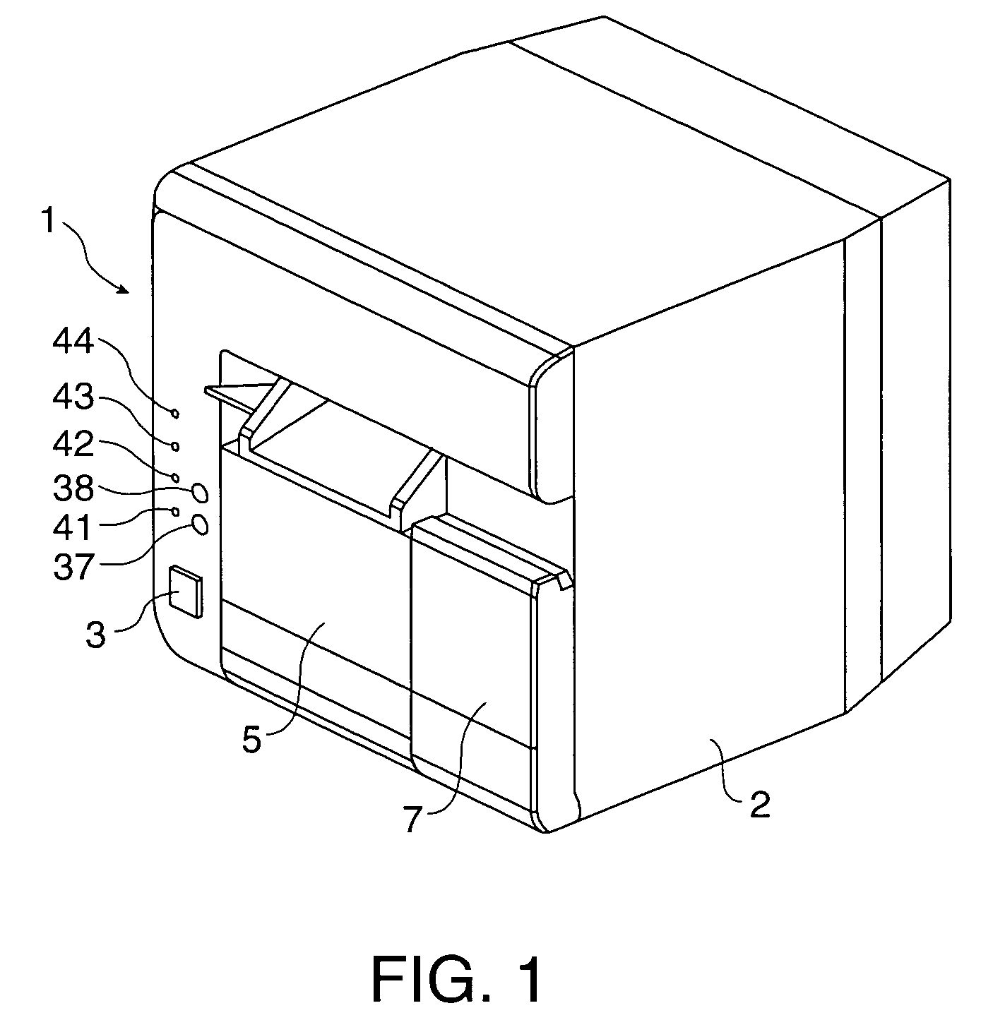
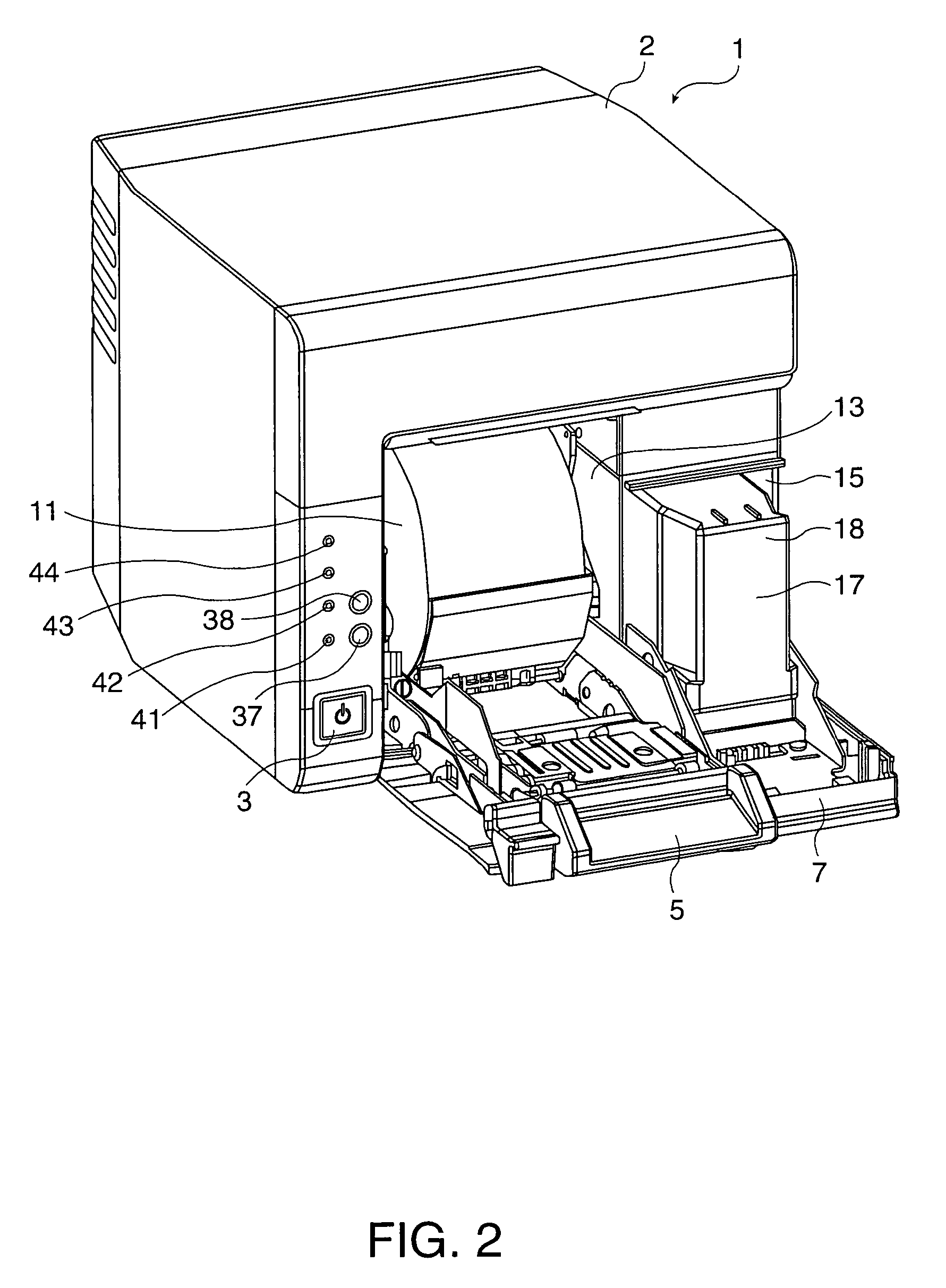
[0038]An inkjet printer 1 according to this embodiment of the invention prints to roll paper 11 using a plurality of colors of ink. As shown in FIG. 1, a roll paper cover 5 and ink cartridge cover 7 are disposed to the front of the case 2, and a power switch 3, cleaning button 37, feed switch 38, and four indicators 41 to 44 are disposed at the front left part of the case 2.

[0039]As shown in FIG. 2, opening the roll paper cover 5 exposes the roll paper compartment 13 where the roll paper 11 is held, and thus enables loading and replacing the roll paper 11.

[0040]As shown in FIG. 3, a carriage 23 carrying a print head 21 is disposed above the roll paper compartment 13. The carriage 23 is supported to move freely widthwise to the paper on a guide member 25 extending widthw...


PUM


Abstract

A cleaning mechanism for cleaning a print head in an inkjet printer with the print head having ink nozzles for discharging ink including a drive control unit which operates the cleaning mechanism at a first process level or a second process level that consumes less ink than the first process level; a timer which counts the elapsed time passed in which the print head is in a no-printing state; and a process selection unit responsive to a predetermined input cleaning command for selecting the first process level when the no-printing state has continued for less than a predetermined time or the second process level when the no-printing state has continued for greater than the predetermined time, based on the value of the timer when the predetermined input cleaning command is received. The predetermined input cleaning command can be received from a cleaning button or from a host computer. The drive control unit operates the cleaning mechanism at the process level selected by the process selection unit according to the predetermined input cleaning command.

Description

BACKGROUND OF THE INVENTION[0001]1. Field of the Invention[0002]The present invention relates generally to an inkjet printer and to a cleaning device and method for cleaning the print head in an inkjet printer. The invention relates more particularly to a cleaning device and method for minimizing ink waste in an inkjet printer from cleaning processes executed in response to an operator command.[0003]2. Description of Related Art[0004]Inkjet printers print text and images on a print medium by discharging ink from the ink nozzles of a print head. Water is typically used as the ink solvent, and if ink is not discharged from the ink nozzles for a certain period of time, the water evaporates and the viscosity of the ink left in the nozzles increases. As a result, the nozzles clog, ink is not discharged or is not discharged at the normal size and speed, resulting in printing defects (referred to below as dropped dots). To prevent this, inkjet printers cover the nozzles with a cap when the...

Claims


Application Information

Patent Timeline
Patent Type & Authority Patents(United States)
IPC IPC(8): B41J2/165
CPCB41J2/1652
Inventor TAGA, SUSUMUKOIKE, TOSHIAKIARAI, JUNICHI
Owner SEIKO EPSON CORP
Learn More