Extender lens apparatus and optical apparatus

a technology of extension lens and optical device, which is applied in the field of extension lens apparatus, can solve the problems of difficult automatic attachment and detachment of large extension lens, large conversion lens, and large conversion lens. achieve good optical performan

Inactive Publication Date: 2010-08-03
CANON KK
View PDF6 Cites 2 Cited by
  • Summary
  • Abstract
  • Description
  • Claims
  • Application Information

AI Technical Summary

Benefits of technology

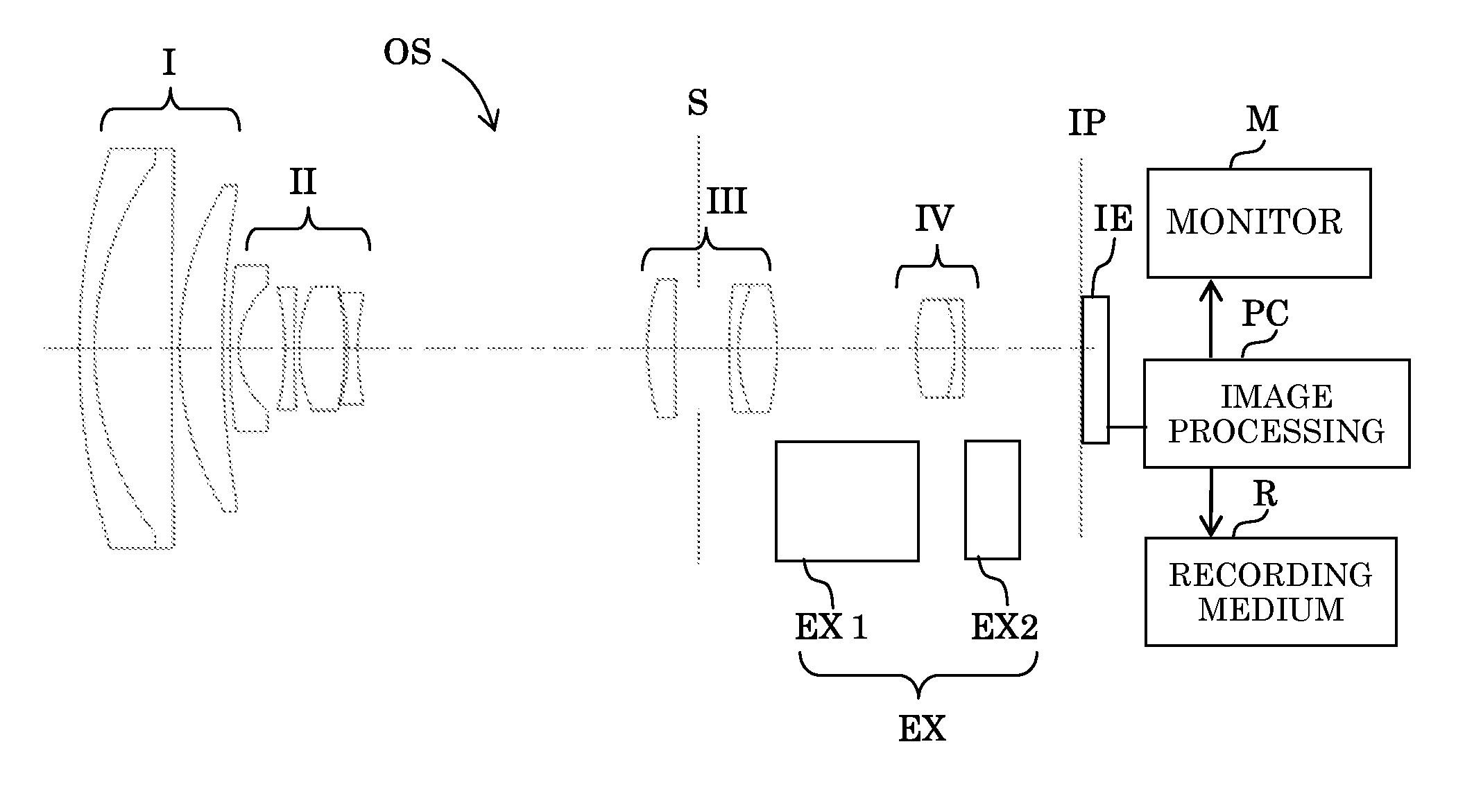
[0009]The present invention provides an extender lens apparatus capable of varying a magnification of an image-forming optical system in a compact optical apparatus while maintaining good optical performance without greatly increasing the entire length of the image-forming optical system.
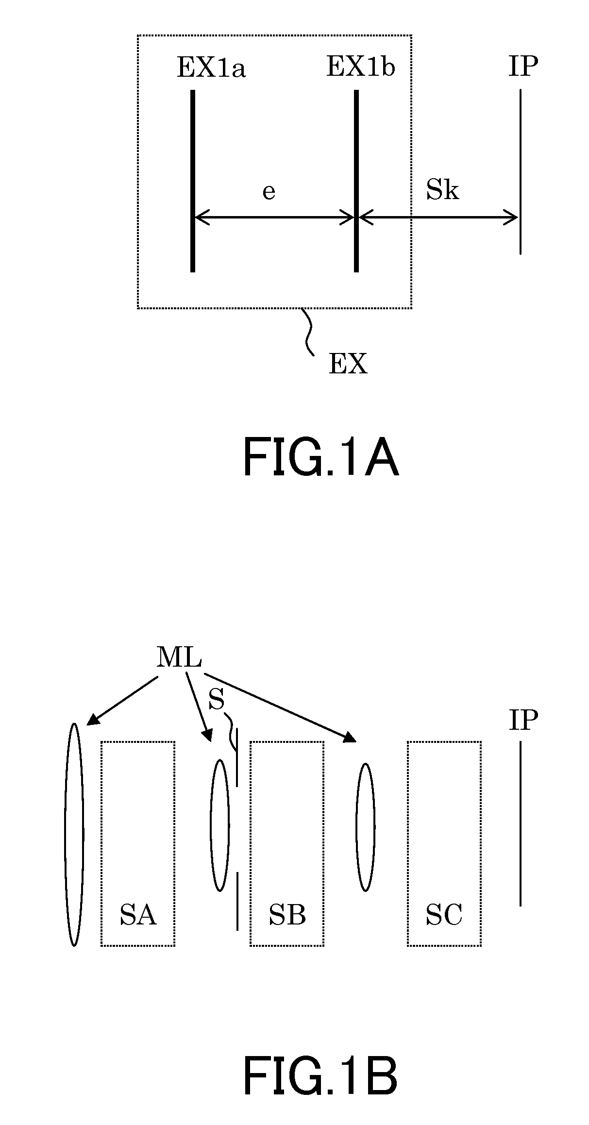
[0010]The present invention provides, according to an aspect thereof, an extender lens apparatus detachably attached to an image-forming optical system including a plurality of main lens units that includes a first main lens unit disposed closest to an object and a second main lens unit disposed between the first main lens unit and an image plane. The apparatus includes a first extender lens unit to be inserted in a space closer to the first main lens unit than the second main lens unit, and a second extender lens unit to be inserted in a space closer to the image plane than the second main lens unit. The first extender lens unit has a magnification increasing effect.

Problems solved by technology

However, the converter lens is often large, and as a result, the entire image-pickup lens to which the converter lens is attached becomes large.
Further, automatic attachment and detachment of a large converter lens is also difficult.
However, when a built-in extender system is used in an image-pickup lens in which the compactness is valued, the extender lens must be inserted into a rather narrow space.
As a result, since the power of the extender lens increases, its optical performance is deteriorated.

Method used


Image

  • Extender lens apparatus and optical apparatus
  • Extender lens apparatus and optical apparatus
  • Extender lens apparatus and optical apparatus

Examples


numerical example of embodiment 1

[0086]

TABLE 1state of the extender lens apparatus>R1 = 42.554D1 = 1.0N1 = 1.84666ν1 = 23.9R2 = 20.481D2 = 5.0N2 = 1.696797ν2 = 55.5R3 = 509.922D3 = 0.5R4 = 20.65D4 = 2.8N4 = 1.772499ν4 = 49.6R5 = 56.456D5 = VARIABLER6 = 39.422D6 = 0.6N6 = 1.882997ν6 = 40.8R7 = 5.519D7 = 3.0R8 = −17.085D8 = 0.6N8 = 1.882997ν8 = 40.8R9 = 62.642D9 = 0.3R10 = 9.742D10 = 3.0N10 = 1.84666ν10 = 23.9R11 = −16.25D11 = 0.2R12 = −11.91D12 = 0.6N12 = 1.785896ν12 = 44.2R13 = 15.84D13 = VARIABLER14 = 16.357D14 = 1.8N14 = 1.74013ν14 = 49.2R15 = 142.777D15 = 1.5R16 = ∞D16 = 2.0R17 = 35.978D17 = 0.6N17 = 1.84666ν17 = 23.9R18 = 10.976D18 = 2.5N18 = 1.51633ν18 = 64.1R19 = −17.404D19 = VARIABLER20 = 12.697D20 = 2.5N20 = 1.696797ν20 = 55.5R21 = −9.883D21 = 0.6N21 = 1.834ν21 = 37.2R22 = −95.156ASPHERICAL SURFACE COEFFICIENTR14k = −6.88486e+00A = 5.07330e−03B = 1.11200e−04C = −1.801387e−06D = 1.96797e−07E = −1.49004e−08F = 3.32099e−10FOCAL LENGTHD4.16 mm66.37 mmD50.4617.65D1318.801.61D199.0410.78

[0087]

TABLE 2the extender ...

numerical example for embodiment 2

[0088]

TABLE 3state of the extender lens apparatus>The values are the same as those in the image-pickup lens in the non-inserted state of Embodiment 1.extender lens apparatus>The values of R1 to R19 are the same as those in theimage pickup lens in the inserted state of Embodiment 1.

numerical example of embodiment 3

[0089]

TABLE 4state of the extender lens apparatus>R1 = 34.479D1 = 1.2N1 = 1.805181ν1 = 25.4R2 = 21.411D2 = 4.0N2 = 1.496999ν2 = 81.5R3 = −199.803D3 = 0.4R4 = 19.055D4 = 2.5N4 = 1.603112ν4 = 60.6R5 = 55.735D5 = VARIABLER6 = 45.792D6 = 0.5N6 = 1.882997ν6 = 40.8R7 = 5.955D7 = 3.4R8 = −31.977D8 = 0.5N8 = 1.696797ν8 = 55.5R9 = 17.991D9 = 0.35R10 = 10.862D10 = 2.0N10 = 1.92286ν10 = 18.9R11 = 27.214D11 = VARIABLER12 = ∞D12 = 0.52R13 = 10.804D13 = 2.1N13 = 1.6935ν13 = 53.2R14 = −36.0145D14 = 3.8R15 = 61.062D15 = 0.5N15 = 1.84666ν15 = 23.9R16 = 8.293D16 = 0.6R17 = 11.522D17 = 2.0N17 = 1.603112ν17 = 60.6R18 = −18.927D18 = VARIABLER19 = −36.977D19 = 1.0N19 = 1.51633ν19 = 64.1R20 = 13.706D20 = VARIABLER21 = 15.438D21 = 3.0N21 = 1.754998ν21 = 52.3R22 = −21.577D22 = 0.8N22 = 1.84666ν22 = 23.9R23 = −48.576R14k = −1.61328+00A = 1.37555e−03B = −2.79283e−04C = 2.40434e−05D = −7.57128e−07FOCAL LENGTHD6.71 mm49.98 mmD50.5415.20D1119.520.62D180.397.00D205.483.00

[0090]

TABLE 5extender lens apparatus>The v...


PUM


Abstract

The extender lens apparatus is detachably attached to an image-forming optical system including a first main lens unit disposed closest to an object and a second main lens unit disposed between the first main lens unit and an image plane. The apparatus includes a first extender lens unit to be inserted in a space closer to the first main lens unit than the second main lens unit, and a second extender lens unit to be inserted in a space closer to the image plane than the second main lens unit. The first extender lens unit has a magnification increasing effect. The apparatus is capable of varying a magnification of the image-forming optical system while maintaining good optical performance without greatly increasing the entire length of the image-forming optical system.

Description

BACKGROUND OF THE INVENTION[0001]The present invention relates to an extender lens apparatus used for an optical apparatus such as a digital still camera, a video camera, and the like.[0002]A variety of front converter systems have been proposed in which the focal length of an image-pickup lens, which is an image-forming optical system installed in an optical apparatus such as an image-pickup apparatus, is lengthened or shortened by attaching a converter lens to an object side of the image-pickup lens (for example, refer to Japanese Patent Laid-Open No. 2005-331851).[0003]The front converter system is capable of easily changing the range of a focal length of an image-pickup lens due to its simple constitution. However, the converter lens is often large, and as a result, the entire image-pickup lens to which the converter lens is attached becomes large. Further, automatic attachment and detachment of a large converter lens is also difficult.[0004]In contrast to such a front converter...

Claims


Application Information

Patent Timeline
Patent Type & Authority Patents(United States)
IPC IPC(8): G02B15/02H04N5/225
CPCG02B15/10
Inventor SAKAI, HIDEKI
Owner CANON KK
Why Eureka
Try Eureka