
System, method and device to preserve protection communication active during a bypass operation

a technology of protection communication and bypass operation, applied in emergency protection circuit arrangements, electrical equipment, parameter calibration/setting, etc., can solve problems such as relay detection of faults or abnormalities, affecting the quality of power line protection, and general inability to maintain current differential protection

Active Publication Date: 2010-07-13
SCHWEITZER ENGINEERING LABORATORIES
View PDF83 Cites 6 Cited by
  • Summary
  • Abstract
  • Description
  • Claims
  • Application Information

AI Technical Summary

Problems solved by technology

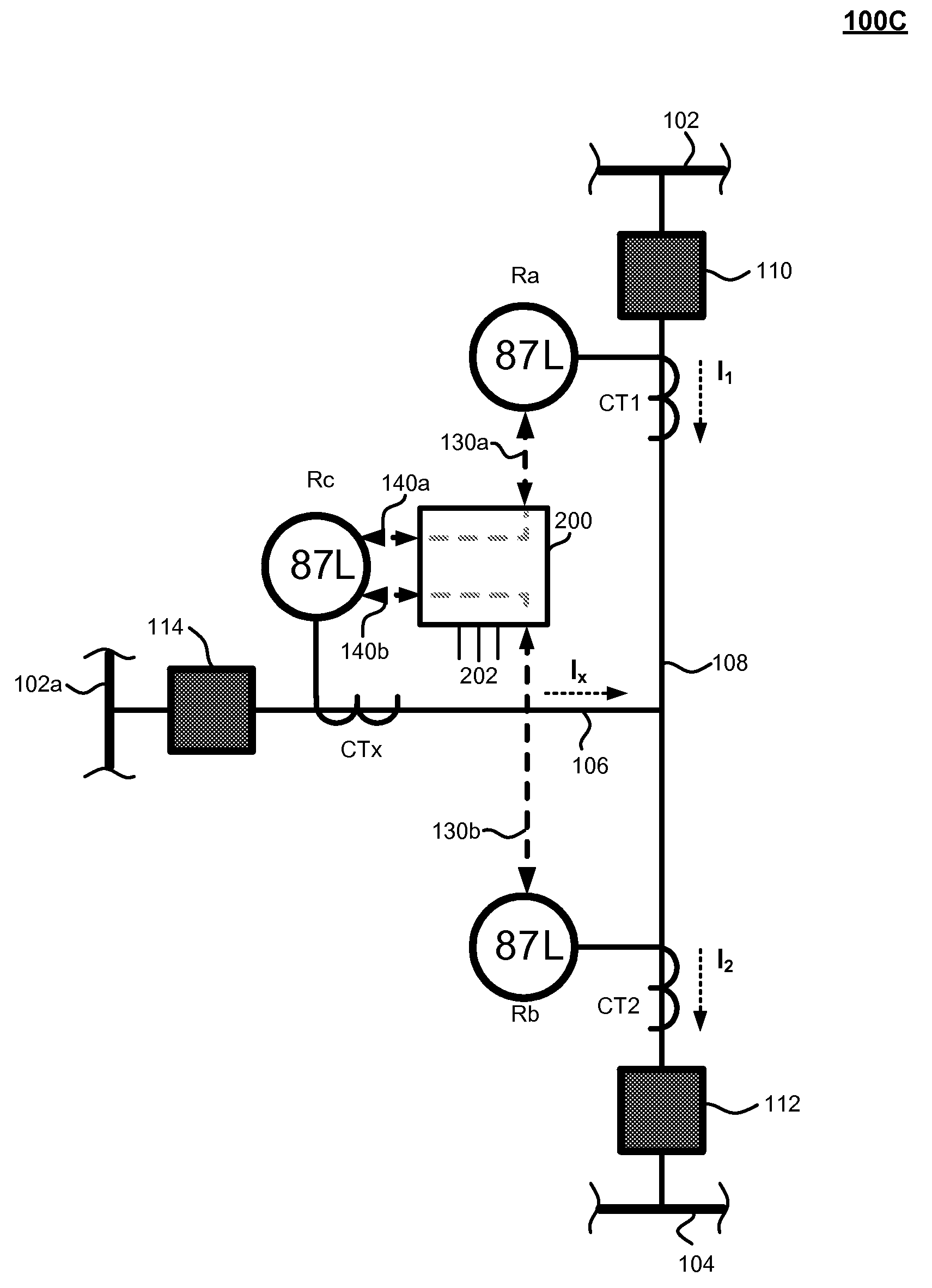
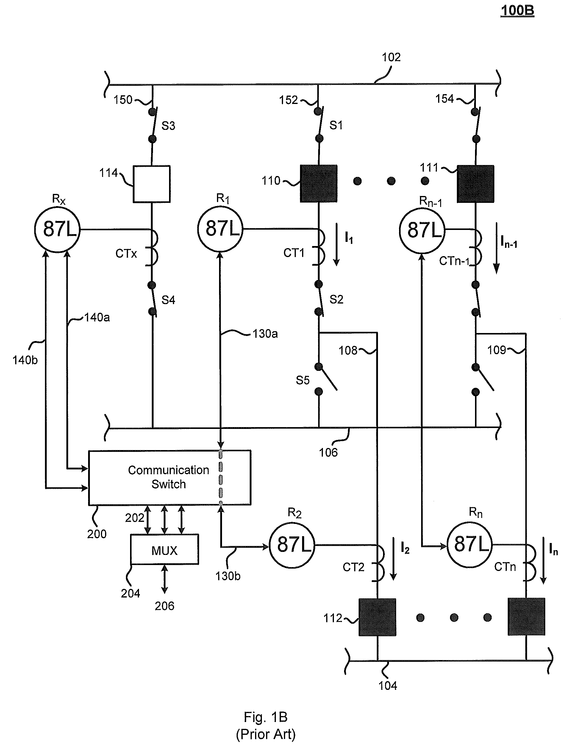
Nevertheless, the arrangement of FIG. 1B poses a number of challenges for current differential protection of power lines.
For example, current differential protection generally cannot be maintained during the entire bypass process due to the resulting parallel lines that feed a protected power line through both the main and transfer buses during the switching process of a breaker bypass operation.
The hypothetical condition of keeping line current differential protection active on the local and remote relays during the switching process, would inaccurately cause these relays to detect a fault or abnormal condition on the power line.
This, however, compromises the quality of the power line protection as step-distance protection is generally known to be slower and less reliable than current differential protection.
Most faults associated with a breaker bypass operation generally occur due to human error.
For example, operators may inadvertently cause a bus-to-ground fault while they intend to create a parallel current path that will allow for isolation of the circuit breaker.
Therefore, during manual modifications to the bus configurations during a bypass operation, the risk of causing a fault is the highest.

Method used


Image

  • System, method and device to preserve protection communication active during a bypass operation
  • System, method and device to preserve protection communication active during a bypass operation
  • System, method and device to preserve protection communication active during a bypass operation

Examples


Embodiment Construction

[0044]The present invention generally relates to a method and apparatus for customization of an IED. Generally, IEDs are used for protecting, monitoring, controlling, metering and / or automating electric power systems and associated power lines. IEDs may include protective devices such as protective relays, or otherwise, RTUs, PLCs, bay controllers, SCADA systems, general computer systems, meters, and any other comparable devices used for protecting, monitoring, controlling, metering and / or automating electric power systems and their associated power lines.

[0045]Although the embodiments described herein are preferably associated with protective devices, such as protective relays including transfer relays, local relays and remote relays, it is contemplated that the embodiments may also be associated with any suitable power system control or protective devices such as those mentioned or described above or below.

[0046]FIG. 2A illustrates an embodiment of the invention for providing prot...


PUM


Abstract

Provided is an intelligent electronic device for protection, monitoring, controlling, metering or automation of electrical power system. The system, method and device of the present invention preserves current differential protection active during a breaker bypass or similar operation. A current differential protection system is coordinated by one relay (transfer), which simultaneously establishes and handles multiple two-terminal 87L protection zones with several relays. This “enhanced multiple-terminal system” requires no change to protection settings on any local or remote relays during a bypass process.

Description

CROSS-REFERENCE TO RELATED APPLICATIONS[0001]None.BACKGROUND OF THE INVENTION[0002]The present invention generally relates to electric power systems including intelligent electronic devices (IEDs) for protecting, monitoring, controlling, metering and / or automating electric power systems and associated power lines. More specifically, the present invention relates to a system, method and device for preserving current differential protection communication active during the process involved in a breaker bypass or similar operation.[0003]Electric utility systems or power systems are designed to generate, transmit and distribute electrical energy to loads. In order to accomplish this, power systems generally include a variety of power system elements such as electrical generators, electrical motors, power transformers, power transmission lines, buses and capacitors, to name a few. As a result, power systems must also include IEDs and procedures to protect the power system elements from ab...

Claims


Application Information

Patent Timeline
Patent Type & Authority Patents(United States)
IPC IPC(8): H02H3/32
CPCH02H3/30H02H7/261H02H3/006
Inventor ORTEGA, JUAN GASTON
Owner SCHWEITZER ENGINEERING LABORATORIES
Learn More