Two-dimensional modulation method for hologram recording and hologram apparatus with encoder for driving SLM displaying boundary portion
a two-dimensional modulation and boundary portion technology, applied in the field of hologram recording carriers, can solve the problems of data reproducing performance degradation, inability to remove all such factors, decoding errors, etc., and achieve the effect of preventing degradation of reproduction performance and allowing information to be stably recorded or reproduced
- Summary
- Abstract
- Description
- Claims
- Application Information
AI Technical Summary
Benefits of technology
Problems solved by technology
Method used
Image

Examples
first embodiment
Mode
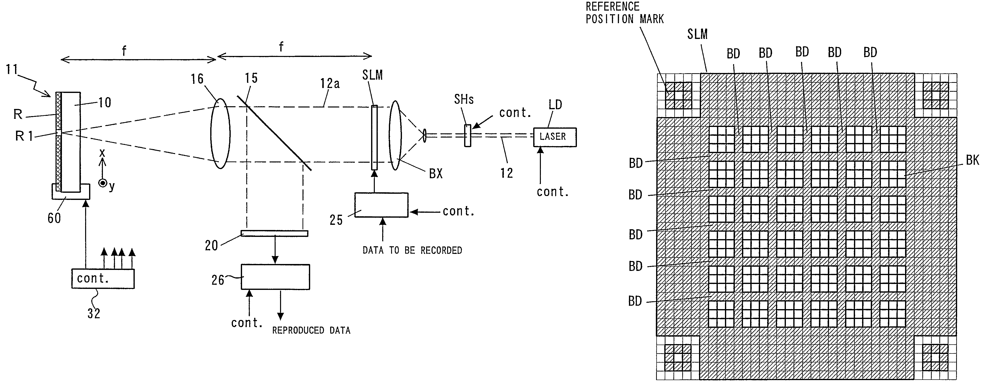
[0066]In the step of generating page data executed within the encoder 25 (or in the controller 32), boundary portion data for the boundary portion is added to each block. The boundary portion data thus added is used as dummy data for formation of boundary portion BD (lattice-like connection area) shielding light. For example, the encoder 25 drives the spatial light modulator SLM such that modulated data for boundary portion BD for 8 blocks as shown in FIG. 7 is generated, and thus generated and two-dimensionally modulated data for 8 blocks as shown in FIG. 8 are superimposed on one another (such that the added boundary portion data is replaced with the data for the connection area (the portion indicated by a broken line in FIG. 8)). As a result, the boundary portion BD (lattice-like connection area) consisting of dark pixels can be defined in advance, and the two-dimensionally modulated blocks can be allocated within the lattice.
[0067]As for specific modulation procedures, a con...
second embodiment
Mode
[0081]In this example of two-dimensional modulation, each 6 bits of the information data is two-dimensionally modulated into the modulation data of 16 bits ((3×3)+7=16 pixels) by referring to a predetermined modulation table (a part of the table is shown in FIG. 13). A new block ((3×3)+7=16 pixels) in which 7 pixels constituting a dark pixel string arranged in an angle bracket shape () are added to 9 bits (9 pixels constitute one block) of light and dark pixels arranged therein in matrix is generated from the information data of six bits according to the modulation table as shown in FIG. 13, for example, (000000)(000001)(000010)(000011)(100100)(100101)(100110)(100 111). The resulting new blocks are simply arranged in the spatial light modulator, thereby generating page data including boundary portion BD consisting of dark pixel strings arranged in lattice.
[0082]Similarly, FIG. 14 shows a part of a modulation table according to which new blocks in each of which dark pixels arrang...
third embodiment
Mode
[0084]In the examples of the above-mentioned lattice forming method, examples are given in which dark pixels arranged in lattice are inserted by using the spatial light modulator SLM having a plurality of pixels arranged in matrix for displaying light pixels which transmit light or dark pixels which shield light, thereby blocks after two-dimensional modulation are connected to each other. In addition thereto, a spatial light modulator having a specific shape may be used.
[0085]For example, as shown in FIG. 15, a construction may also be adopted in which the pixels of the spatial light modulator are partitioned into blocks each having the same number of pixels as that of one block BK after two-dimensional modulation (or as the integral multiple of the pixels of one block BK), and the pre-partitioned blocks BK are arranged in lattice having a space in between so as to have the structure of the boundary portion BD which shields light. That is to say, as shown in FIG. 16, the spatial...
PUM
| Property | Measurement | Unit |
|---|---|---|
| incident angle | aaaaa | aaaaa |
| optical interference | aaaaa | aaaaa |
| width | aaaaa | aaaaa |
Abstract
Description
Claims
Application Information
 - R&D
- Intellectual Property
- Life Sciences
- Materials
- Tech Scout
- Unparalleled Data Quality
- Higher Quality Content
- 60% Fewer Hallucinations
Browse by: Latest US Patents, China's latest patents, Technical Efficacy Thesaurus, Application Domain, Technology Topic, Popular Technical Reports.
© 2025 PatSnap. All rights reserved.Legal|Privacy policy|Modern Slavery Act Transparency Statement|Sitemap|About US| Contact US: help@patsnap.com