
System and method for controlling wind turbine actuation

a technology of wind turbines and actuators, applied in the direction of electric generator control, machines/engines, transportation and packaging, etc., can solve the problems of reducing the efficacy of energy capture and tower fatigue reduction, the cost of those measurement systems is still too high and economically disadvantageous, and the effect of reducing the fatigue of the tower

Inactive Publication Date: 2010-07-13
GENERAL ELECTRIC CO
View PDF13 Cites 48 Cited by
  • Summary
  • Abstract
  • Description
  • Claims
  • Application Information

AI Technical Summary

Benefits of technology

"The patent describes a wind turbine system that includes sensors to measure various factors such as blade pitch angles, rotational speed, and nacelle yaw. The system also includes a controller to adjust the pitch angle of the blades based on these measurements, as well as the tower deflection in real-time. The technical effect of this system is to improve the efficiency and performance of wind turbines by optimizing the pitch angle of the blades based on the measured factors, resulting in better energy production."

Problems solved by technology

Lags and delays on the estimation of the effective wind speed lead to reduced efficacy in energy capture and tower fatigue reduction.
While the foregoing solutions are very effective, the cost of those measurement systems is still much too high and economically disadvantageous.
Further, the use of adhesives, cements and / or bonding agents is generally highly sensitive to the electrode-tower contact and is therefore not optimal for large numbers of measurement points over a large area of a wind tower.

Method used


Image

  • System and method for controlling wind turbine actuation
  • System and method for controlling wind turbine actuation
  • System and method for controlling wind turbine actuation

Examples


Embodiment Construction

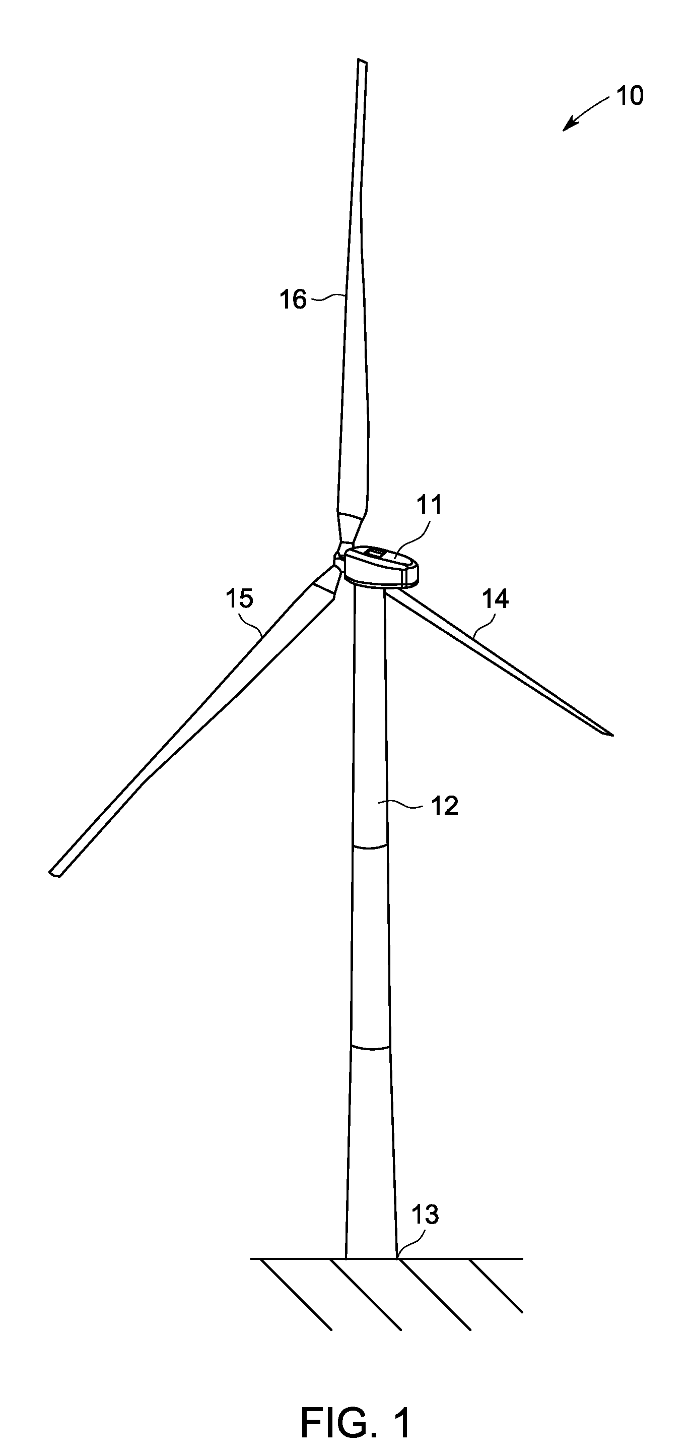
[0036]In some configurations and referring to FIG. 1, a wind turbine 10 comprises a nacelle 11 housing a generator (e.g. 26 in FIG. 2). Nacelle 11 is mounted atop a tall tower 12. Wind turbine 10 also comprises a rotor (e.g. 22FIG. 2) that includes one or more rotor blades 14, 15, 16 attached to a rotating hub. Although wind turbine 10 illustrated in FIG. 1 includes three rotor blades 14, 15, 16, there are no specific limits on the number of rotor blades required by the embodiments described herein.

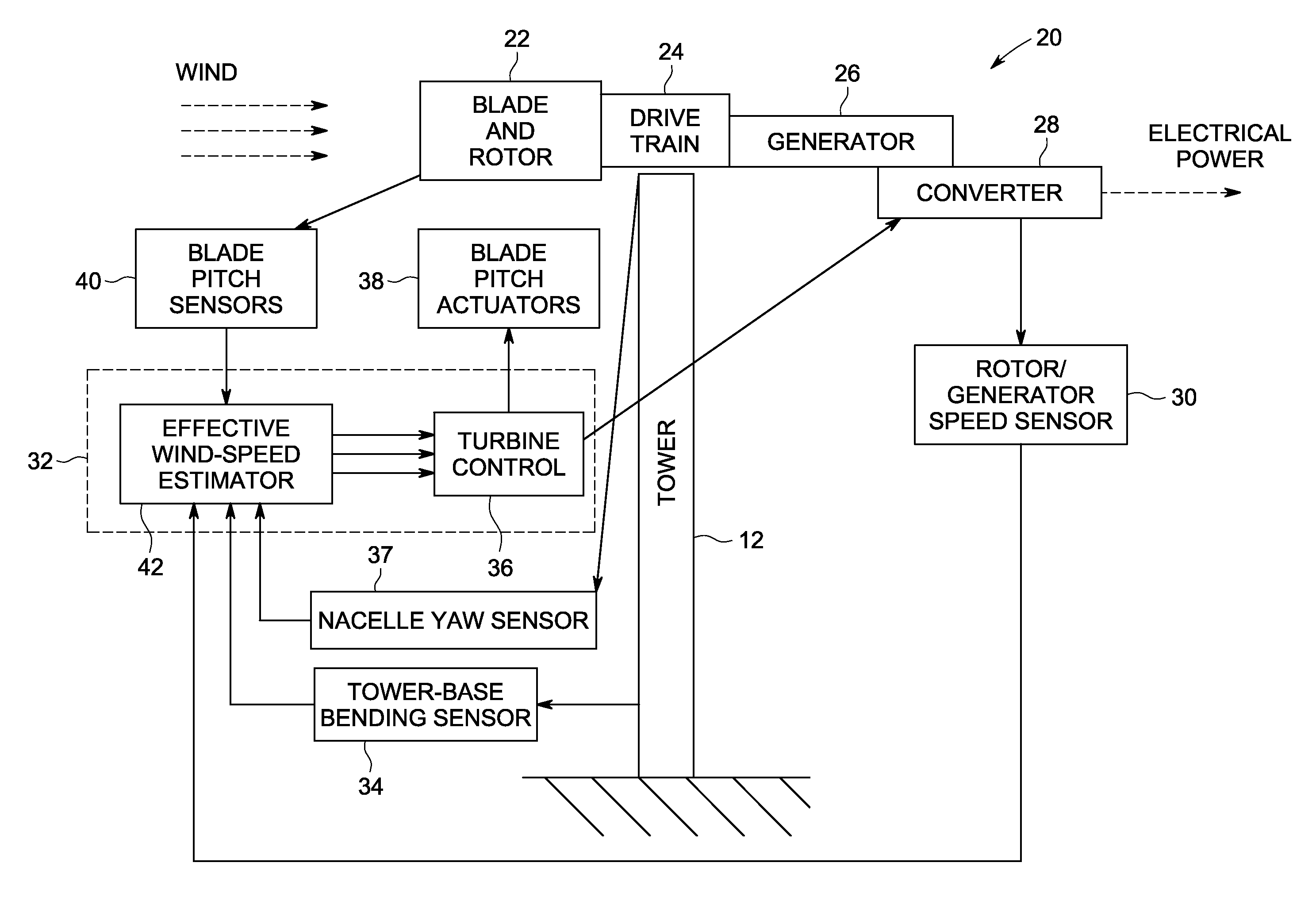
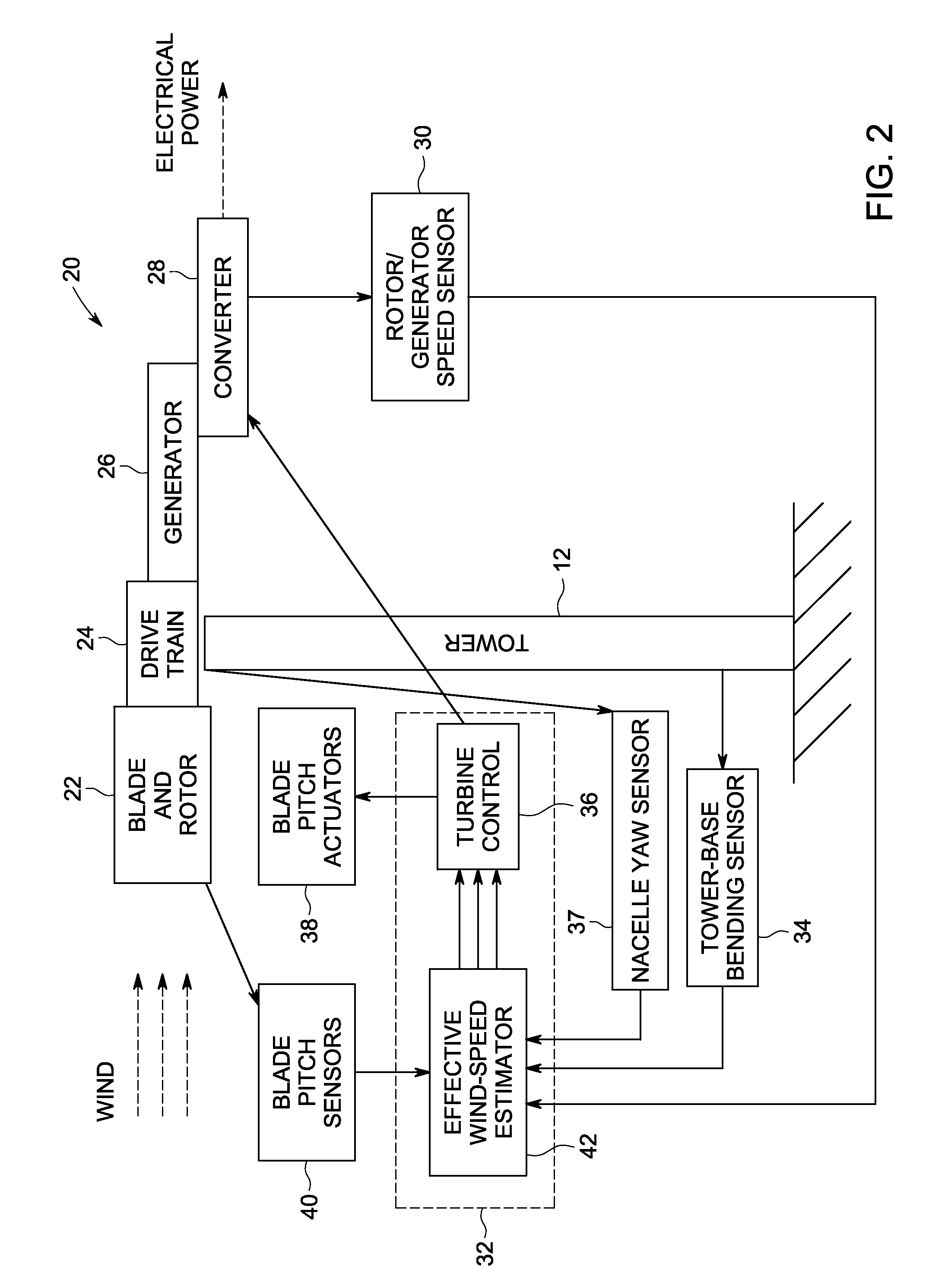
[0037]In some configurations and referring to FIGS. 1 and 2, various components are housed in nacelle 11 atop tower 12 of wind turbine 10. The height of tower 12 is selected based upon factors and conditions known in the art. In some configurations, one or more controllers 32 including algorithmic software are used for wind-speed monitoring and turbine control and may be based on distributed or centralized control architectures.

[0038]In some configurations, one or more variable blade pitc...


PUM


Abstract

A wind turbine includes a plurality of wind turbine blades attached to a rotor positioned atop a tower affixed to a tower foundation. At least one blade pitch sensor is configured to measure blade pitch angles for one or more of the wind turbine blades. A rotor / generator speed sensor is configured to measure the rotational speed of the wind turbine rotor, a corresponding wind turbine generator, or both. A wind turbine nacelle yaw sensor is configured to measure the nacelle yaw, while at least two tower-base bending sensors are configured without use of adhesives, cements or bonding agents to provide large-area measurement of tower deflection. A controller is configured to adjust the pitch angle of one or more of the wind turbine blades in response to the measured one or more blade pitch angles, the measured rotational speed, the measured nacelle yaw and measured tower longitudinal deflection.

Description

BACKGROUND[0001]This invention relates generally to wind turbines, and more particularly to methods and apparatus for controlling wind turbine actuation to compensate for variations in wind speed.[0002]Recently, wind turbines have received increased attention as environmentally safe and relatively inexpensive alternative energy sources. With this growing interest, considerable efforts have been made to develop wind turbines that are reliable and efficient.[0003]Generally, a wind turbine includes a rotor having multiple blades. The rotor is mounted to a housing or nacelle, which is positioned on top of a truss or tubular tower. Utility scale grade wind turbines (i.e., wind turbines designed to provide electrical power to a utility grid) can have large rotors (e.g., 70 or more meters in diameter). Blades on these rotors transform wind energy into a rotational torque or force that drives one or more generators that may be rotationally coupled to the rotor through a gearbox. The gearbox...

Claims


Application Information

Patent Timeline
Patent Type & Authority Patents(United States)
IPC IPC(8): F03D9/00
CPCF03D7/0224F03D7/043F05B2260/821F05B2270/32F05B2270/327F05B2270/328F05B2270/329F05B2270/331Y02E10/723Y02E10/72
Inventor KAMMER, LEONARDO CESARFAIDI, WASEEM IBRAHIMQUEK, SHU CHINGBAEHMANN, PEGGY LYNN
Owner GENERAL ELECTRIC CO
Learn More