
Railway vehicle wheel with elastic rubber suspension

a technology of rubber suspension and rail vehicle, which is applied in the direction of high resiliency wheels, vehicle components, tire parts, etc., can solve the problems of reducing affecting the radial area of the rubber insert, and essentially subjecting the rubber insert to shear stress, so as to achieve sufficient clearance and prevent stress concentration

Active Publication Date: 2010-06-15
BOCHUMER VER VERKEHRSTECHNIK GMBH
View PDF16 Cites 6 Cited by
  • Summary
  • Abstract
  • Description
  • Claims
  • Application Information

AI Technical Summary

Benefits of technology

[0007]The invention, in one embodiment, features a rubber-sprung rail wheel that even in the case of small wheel diameters, as used for example in low-floor carriages, provides good axial rigidity and good radial spring characteristics.
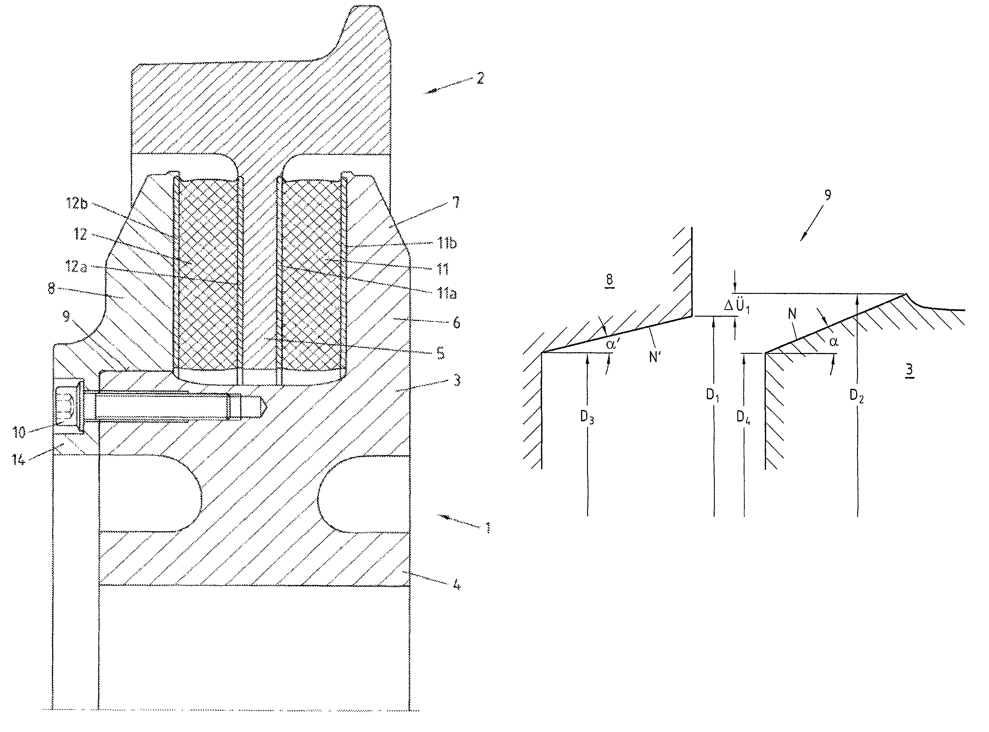
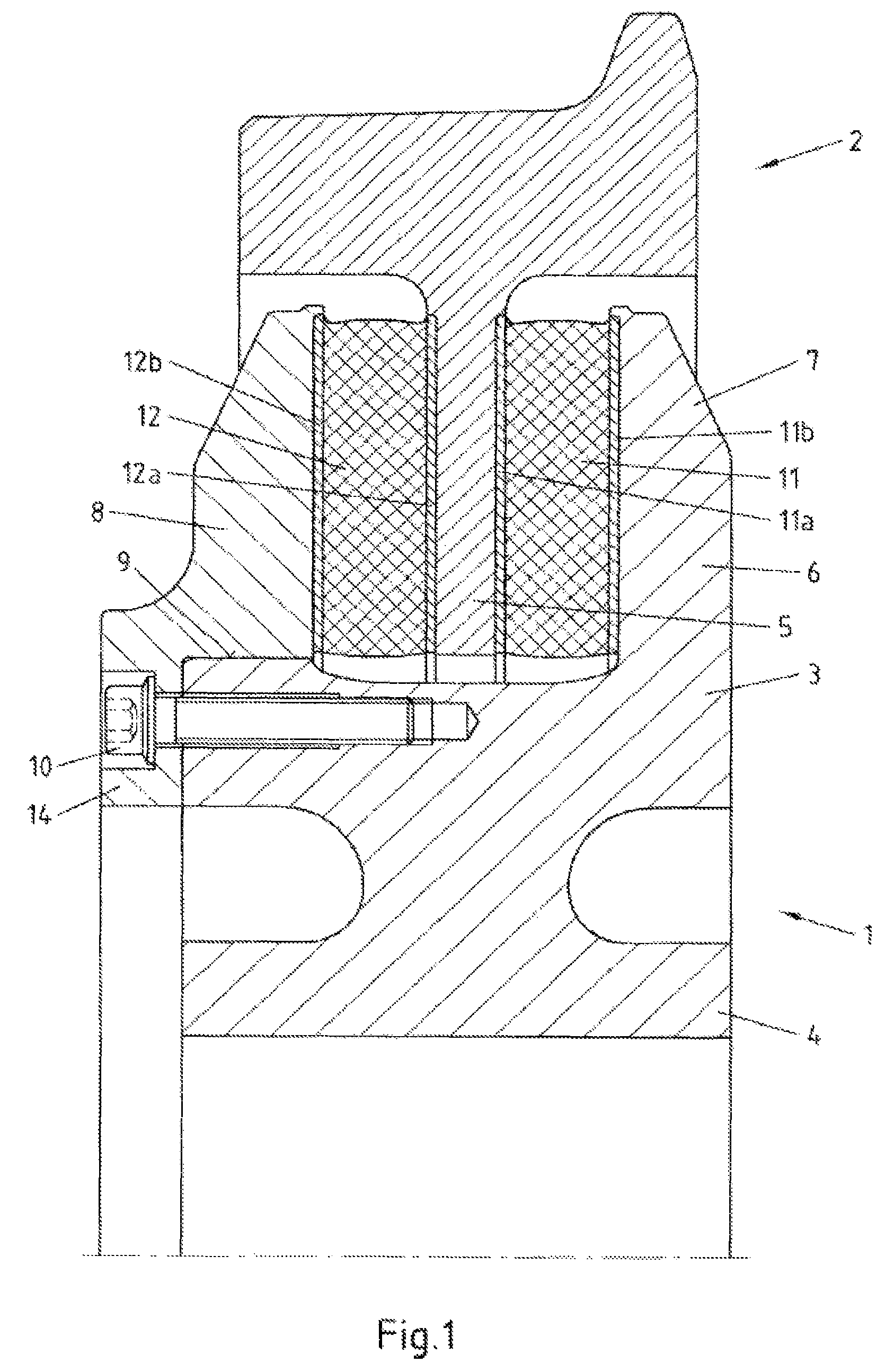
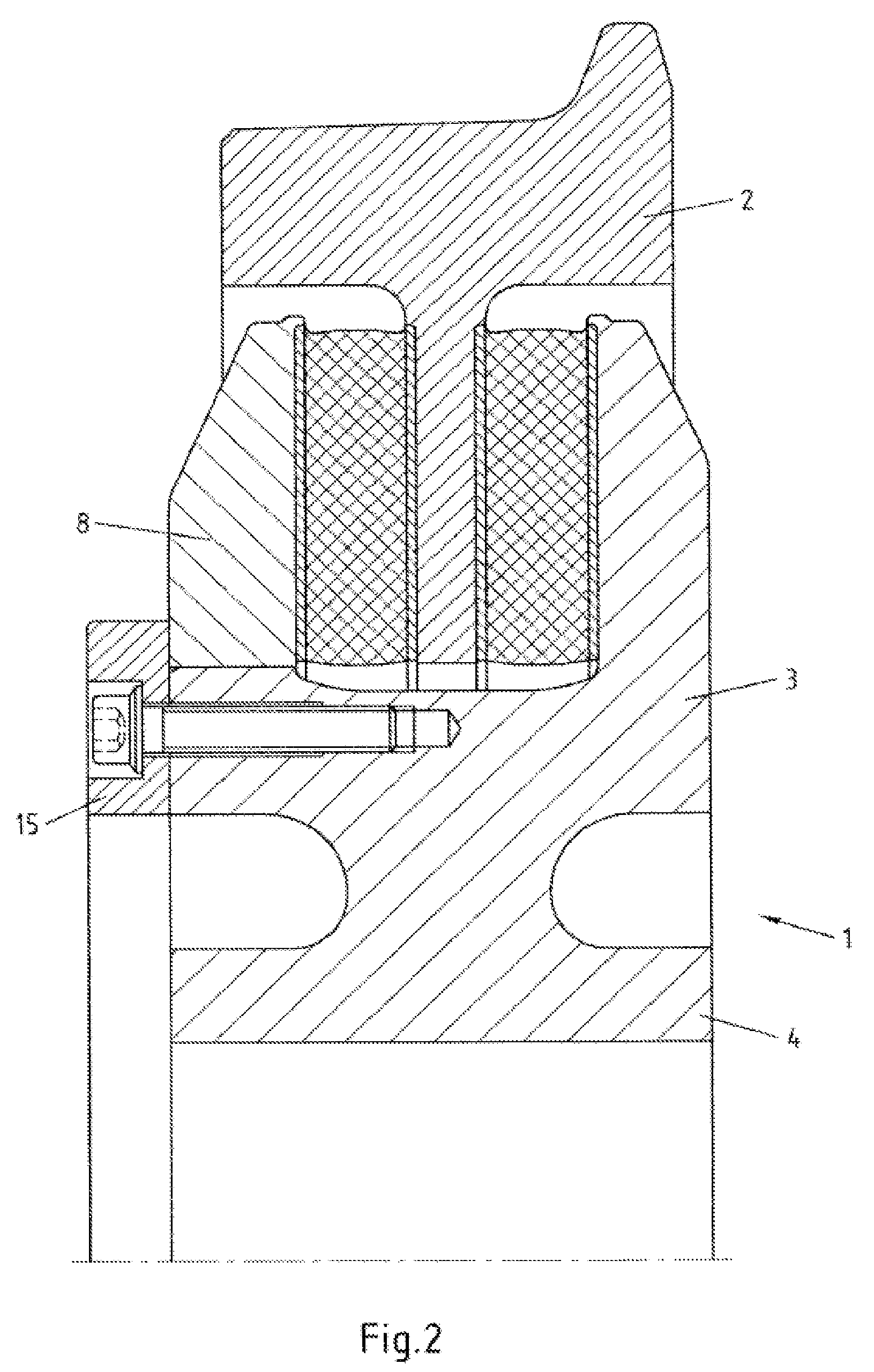
[0009]In the rail wheel according to the invention, by selecting the various conicities of the cones of the interference fit, a situation is achieved in which the pressed-on flange, taking into account its elastic deformation, on the one hand is securely held on the cone of the wheel rim, and on the other hand the rubber insert is optimally prestressed over its entire radial width. In this arrangement the screw bolt essentially only assumes the function of holding the flange on the seat. Said screw bolt is practically not subjected to any load as a result of the restoring force of the rubber insert. Because of the new arrangement of the flange on the wheel rim, the entire space between the web and the flanges is available for accommodating the rubber insert. When compared to the known design with the screw bolts that pass through the rubber insert, an additional rubber volume of up to 30% is gained. This has a positive effect on the ability of the rubber insert to withstand shear stress. This also makes it possible to achieve comparatively low design heights.
[0016]In order to, on the one hand, provide sufficient clearance to the web and to the rubber insert during spring deflection, and in order to, on the other hand, prevent stress concentration at the points of transition between the wheel rim and the flanges, on its outer periphery in the region of the rubber insert the wheel rim can comprise a flat circumferential spring deflection bed for the web of the wheel tire and the rubber insert, wherein the radius of curvature of the rim areas of said spring deflection bed becomes increasingly smaller towards the outside.

Problems solved by technology

However, this arrangement is associated with a disadvantage in that when subjected to vertical loads the rubber insert is essentially subjected to shear stress.
While in this way even axial prestress in the rubber insert can be achieved over the diameter, this type of bracing is, however, associated with a loss of rubber volume.
However, in various applications, in particular in the case of low-floor carriages, where comparatively small wheel diameters are required, it is not possible to provide a larger radial area in order to accommodate more rubber volume.

Method used


Image

  • Railway vehicle wheel with elastic rubber suspension
  • Railway vehicle wheel with elastic rubber suspension
  • Railway vehicle wheel with elastic rubber suspension

Examples


Embodiment Construction

[0026]The rail vehicle wheel shown in FIG. 1 is designed for low-floor vehicles. It comprises a disc wheel body 1 and a wheel tire 2. The disc wheel body 1 comprises a wheel rim 3 and a wheel hub 4. The wheel tire 2 comprises a circumferential inside middle web 5. The wheel rim 3 comprises two flanges 7, 8, of which one flange 7 is connected in one piece to the wheel rim 3, while the other flange 8, by means of an interference fit 9, is seated on the wheel rim 3 and is additionally held by screw bolts. The wheel tire 2 is connected to the wheel rim 3 by way of a rubber insert that comprises two flat rings 11, 12, on the outsides of which flat rings 11, 12, rings 11a, 11b, 12a, 12b are molded on. The rings 11, 12 that form the rubber insert have a shore hardness of 60 to 85 and are loaded with very considerable axial prestress. Their thickness is compressed by 5 to 17%. Due to this very considerable axial prestress that is to be produced by the flange 8 the interference fit 9 is desi...


PUM


Abstract

A rubber-sprung wheel for rail vehicles includes a wheel tire which is connected to a wheel rim by a rubber insert that is formed by two flat rings that are arranged so as to be essentially vertical in relation to a wheel axle. The two flat rings are held, under considerable axial prestress, between an inner circumferential middle web of the wheel tire and two outer flanges of the wheel rim. At least one of the flanges is seated on the wheel rim with an interference fit that is designed as a conical press fit, such that a cone of the flange in a stress-free state has a lesser conicity than does a cone of the wheel rim, and in a pressed-on state rests on an entire surface against the cone of the wheel rim, at an even surface pressure across an entire width of the interference fit.

Description

CROSS-REFERENCE TO RELATED APPLICATIONS[0001]This application is a National Phase Application of International Application No. PCT / EP2006 / 063731, filed Jun. 30, 2006, which claims the benefit of and priority to German Application No. 10 2005 030 966.6, filed Jun. 30, 2005, which is owned by the assignee of the instant application. The disclosure of each of the above applications is incorporated herein by reference in its entirety.FIELD OF THE INVENTION[0002]The invention relates to a rubber-sprung rail wheel in which a wheel tire is connected to a wheel rim by way of a rubber insert that is formed by two flat perforation-free rings that are arranged so as to be inclined to vertical in relation to the wheel axle, wherein the rings are exclusively held, under axial prestress, between supporting surfaces that are arranged so as to be inclined to vertical in relation to the wheel axle and that are formed by a circumferential inner middle web of the wheel tire and two outer flanges of th...

Claims


Application Information

Patent Timeline
Patent Type & Authority Patents(United States)
IPC IPC(8): B60B17/00B60B9/10
CPCB60B17/0013B60B17/0034B60B17/0068B60B17/0058B60B17/0062B60B17/0041
Inventor MURAWA, FRANZSCHUMACHER, BJORN
Owner BOCHUMER VER VERKEHRSTECHNIK GMBH
Learn More