
Loudspeaker mounting mechanism

a technology for loudspeakers and mounting mechanisms, which is applied in the field of loudspeakers, can solve the problems of difficult repositioning of the loudspeaker housing or removing it without significant effort or potential damage to the surface, and achieve the effect of convenient mounting

Inactive Publication Date: 2010-06-08
HARMAN INT IND INC
View PDF52 Cites 41 Cited by
  • Summary
  • Abstract
  • Description
  • Claims
  • Application Information

AI Technical Summary

Benefits of technology

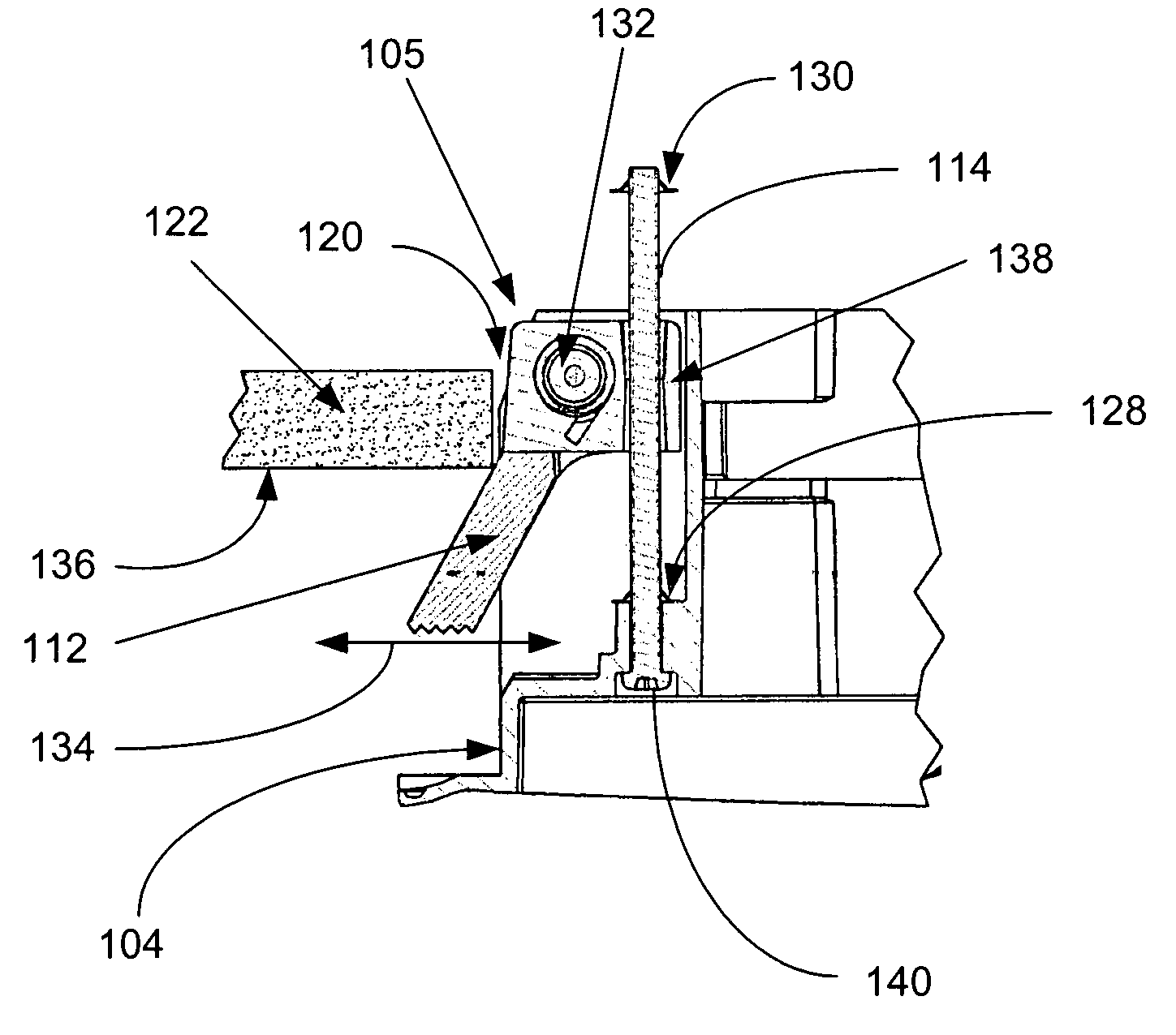
This invention is a mechanism for easily mounting and removing a loudspeaker housing in a surface. It includes a spring-loaded arm that is attached to the loudspeaker housing. When the arm comes in contact with the surface, it compresses inward and aligns with the back side of the surface, securing the housing in place. The mechanism can be tightened or loosened by adjusting the position of the shaft. The housing can be easily removed by compressing the arm inward. The technical effect of this invention is to provide a simple and effective way to mount and remove loudspeakers in different surfaces.

Problems solved by technology

However, this approach is difficult because it requires the loudspeaker to be placed into proper position within the opening in the surface and to be properly attached to the opening while maintaining the proper position.
Additionally, this approach is generally inflexible and permanent in nature because once the loudspeaker housing is attached to the opening it is difficult to reposition the loudspeaker housing or remove it without significant effort or potential damage to the surface.

Method used


Image

  • Loudspeaker mounting mechanism
  • Loudspeaker mounting mechanism
  • Loudspeaker mounting mechanism

Examples


Embodiment Construction

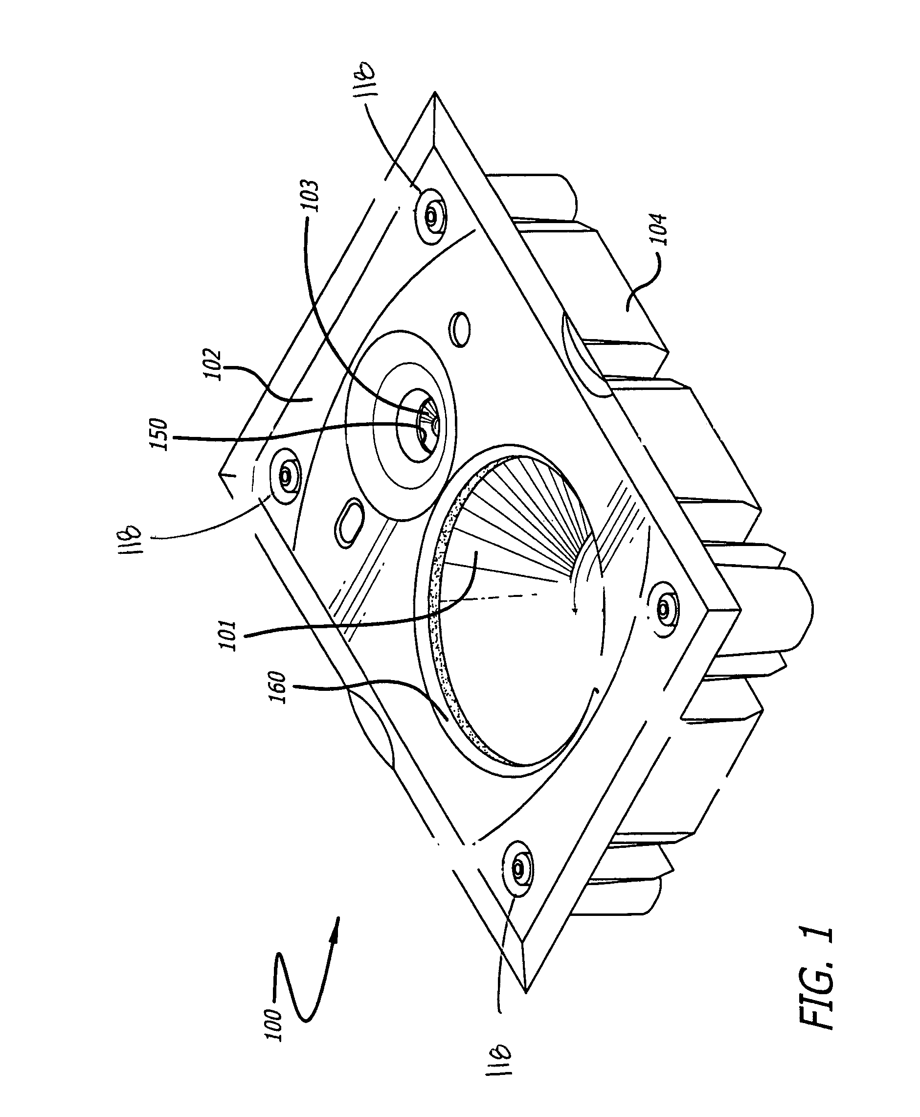
[0026]FIG. 1 is a perspective view of a loudspeaker containment system 100 capable of being mounted within an opening in a surface (not shown), such as a wall or ceiling. As illustrated by FIG. 1, the loudspeaker containment system 100 includes a housing 104, which may be inserted into an opening formed in a wall or other surface. The loudspeaker housing 104 is generally positioned flush against the surface and includes a baffle 102 that is positioned within a recessed area in the loudspeaker housing 104. The baffle 102 will generally include at least one opening 160 for receiving and incorporating at least one loudspeaker 101. As illustrated, the baffle 102 may also include a second opening 150 for receiving a second loudspeaker transducer 103, such as a tweeter. Furthermore, each baffle 102 may include four isolation openings 118 at each of its corners for securing the baffle 102 to the housing 104.

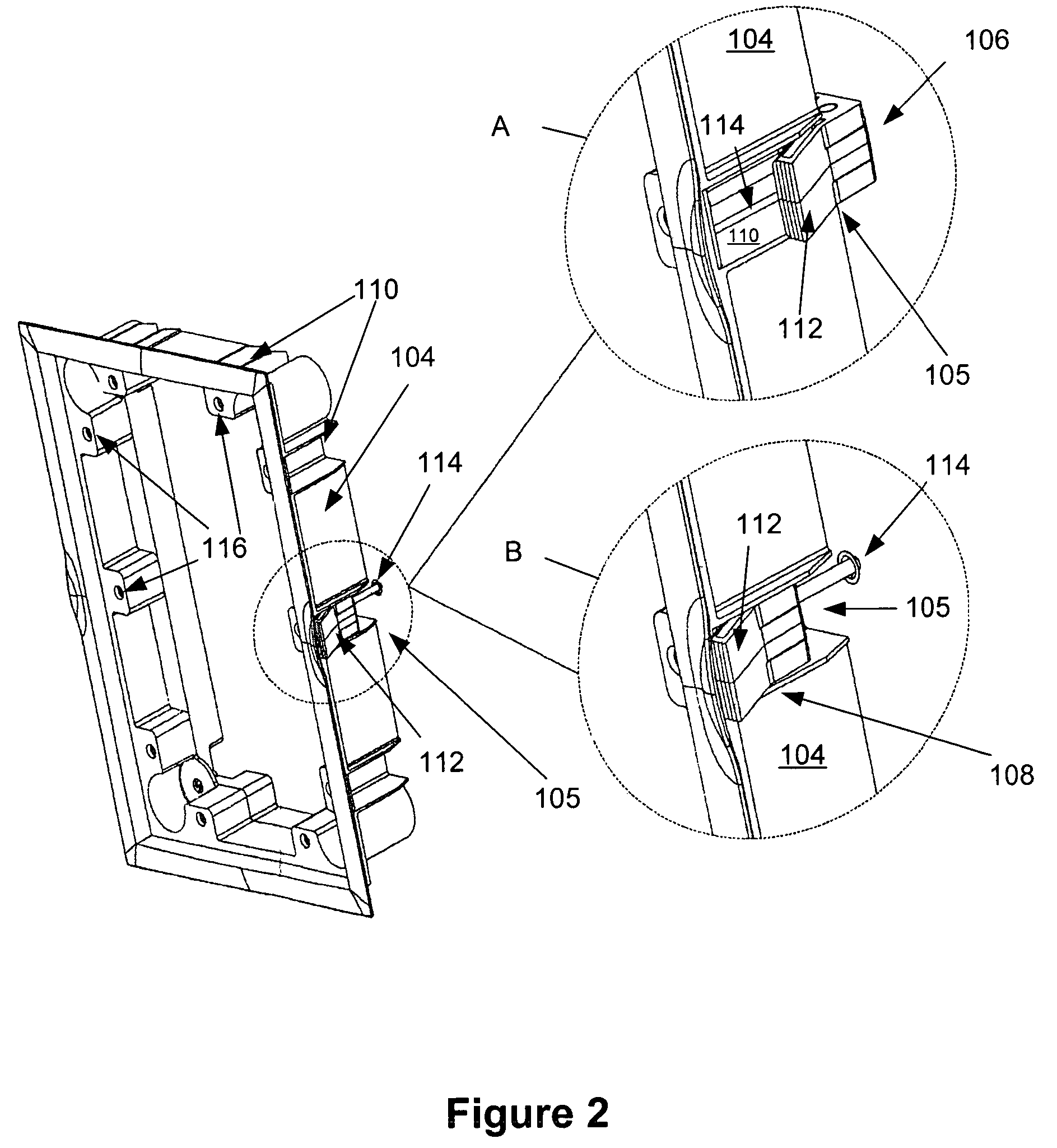
[0027]FIG. 2 is a perspective view of the loudspeaker housing 104 showing an exampl...


PUM


Abstract

This invention provides a spring loaded mounting mechanism for easily mounting and removing a loudspeaker housing within an opening in a surface. The mounting mechanism includes a shaft connected to the loudspeaker housing. Attached to the shaft is a spring actuated arm. The actuated arm is compressed inward toward the housing by the side walls of the surface surrounding the opening when the housing is being positioned within the opening. At a certain point when the housing is inserted far enough into the opening, the actuated arm will lose contact with the side walls of the surface surrounding the opening and will expand to its open position. In its open position, the arm is positioned just behind or against the back face of the surface surrounding the opening, locking the housing into the opening in the surface. The invention further allows for the spring actuated arm to be tightened against or moved away from the back face of the surface by adjusting the positioning of the shaft. To remove the housing from the opening, the spring actuated arm may be moved away from the back face of the surface surrounding the opening by compressing the arm inward toward the housing. The arm may be compressed inward through the use of a device or by the hand of a user. Once the arm is compressed inward, the housing may be easily removed from the opening.

Description

[0001]This application claims priority to U.S. Provisional Application Serial No. 60 / 399,791 filed on Jul. 31, 2002, which is incorporated into this application by reference.BACKGROUND OF THE INVENTION[0002]1. Field of the Invention.[0003]This invention generally relates to the field of loudspeakers. In particular, the invention relates to a system capable of latching the loudspeaker housing within a surface.[0004]2. Related Art.[0005]Installing a loudspeaker into a surface such as a wall and / or ceiling generally includes cutting an opening into the surface to insert the loudspeaker housing into the opening. The loudspeaker housing may be flush against the surface and have a recessed area to receive a baffle that covers the opening and loudspeaker housing. The baffle may incorporate at least one loudspeaker. The loudspeaker housing may be first secured in the surface and then the baffle (with at least one loudspeaker) may be secured to the loudspeaker housing.[0006]At present, mount...

Claims


Application Information

Patent Timeline
Patent Type & Authority Patents(United States)
IPC IPC(8): G12B9/00H04R1/28
CPCH04R1/2873
Inventor DECANIO, WILLIAM ANDREWADLEY, PAUL NELSONHAWKINS, BERNARD
Owner HARMAN INT IND INC
Learn More