
Integrated transceiver with envelope tracking

a transceiver and envelope tracking technology, applied in the direction of transmission, gain control, amplifier modification to reduce noise influence, etc., can solve the problems of rf power amplification, low rf power amplification, and low amplifier efficiency

Inactive Publication Date: 2010-05-11
COMMSCOPE TECH LLC
View PDF19 Cites 110 Cited by
  • Summary
  • Abstract
  • Description
  • Claims
  • Application Information

AI Technical Summary

Problems solved by technology

RF power amplification techniques, and particularly RF power amplification techniques used for wireless applications, have inherent drawbacks to which the industry continues to direct its efforts.
Amplifier efficiency, which is generally defined as the level of RF power that may be achieved at the output signal compared to the power that is input into the overall amplification process, is conventionally somewhat low in wireless applications.
Another drawback in RF power amplification, which must be addressed and taken into account with any methods for improving efficiency, is signal distortion.
Non-linearities of the amplifier, as well as other factors, contribute to the distortion.

Method used


Image

  • Integrated transceiver with envelope tracking
  • Integrated transceiver with envelope tracking
  • Integrated transceiver with envelope tracking

Examples


Embodiment Construction

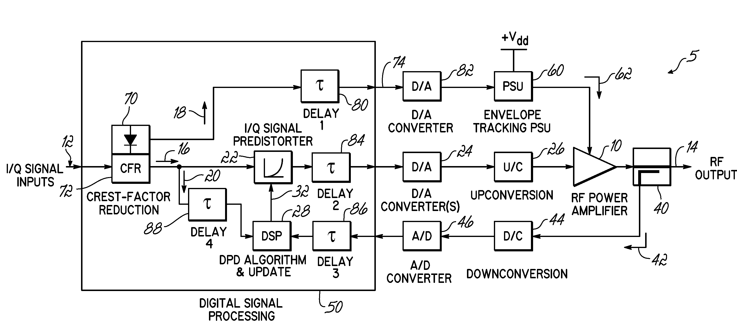
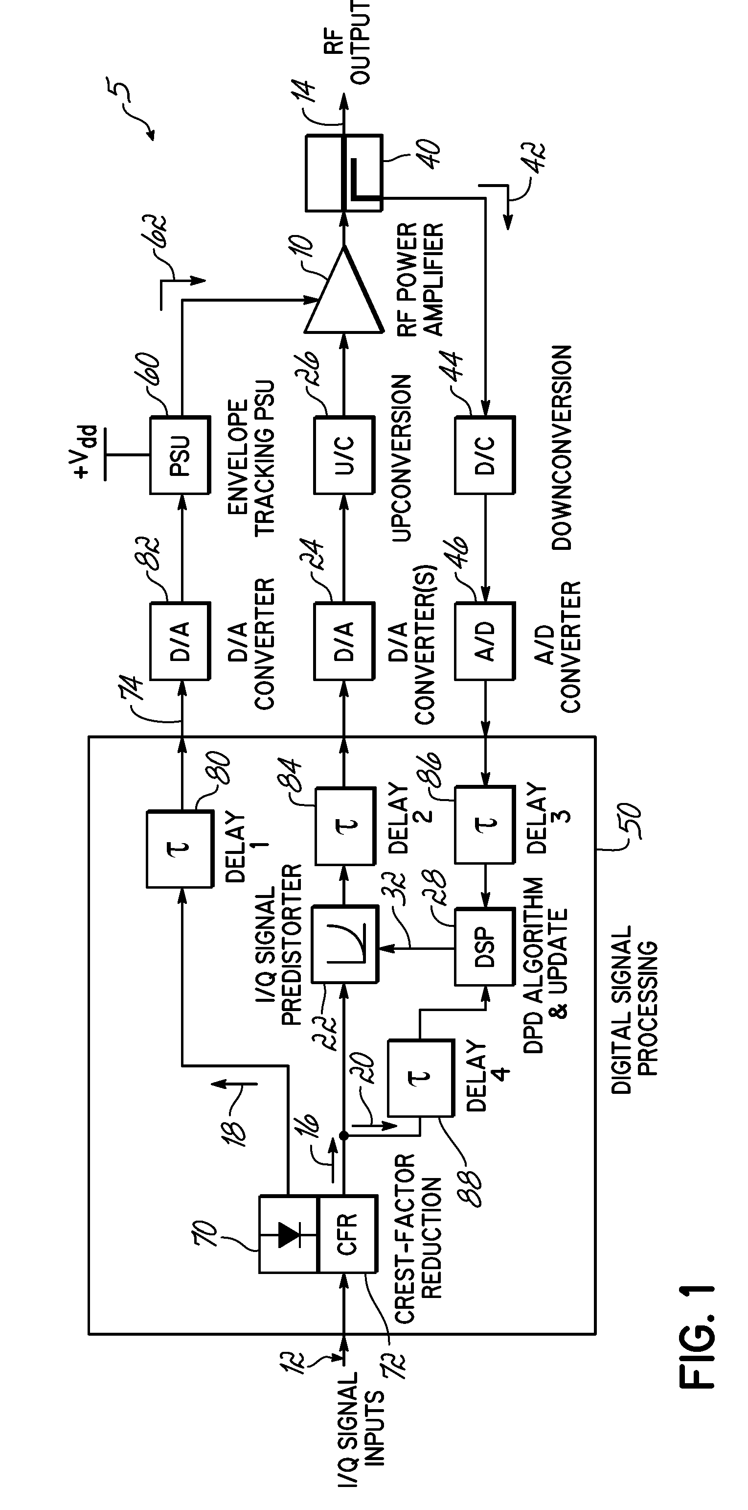
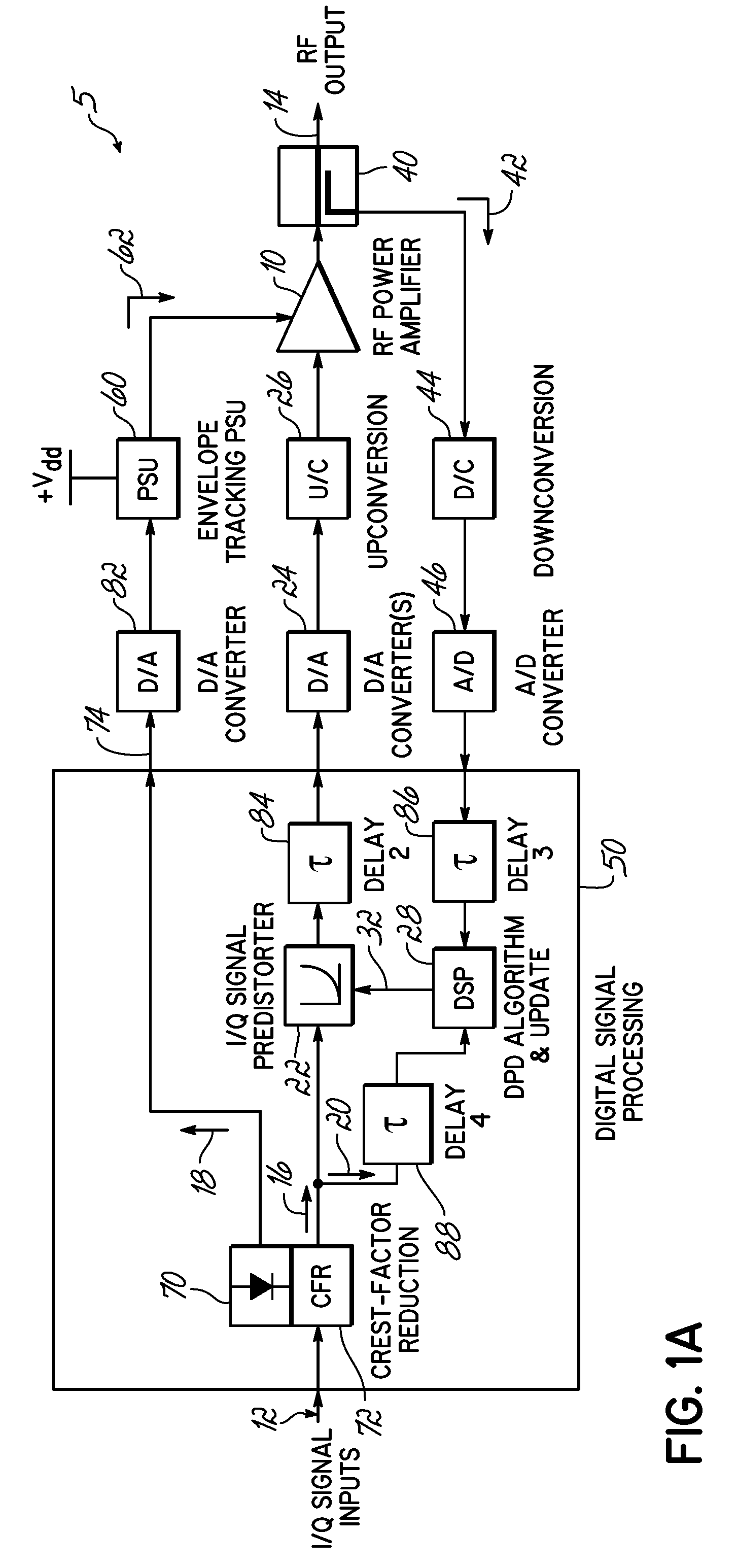
[0013]The present invention addresses the above-noted drawbacks in the prior art, and specifically addresses the utilization of an envelope tracking power supply in a transceiver. Specifically, the present invention utilizes digital signal processing within a transceiver to perform envelope extraction and provide appropriate Delay matching of the envelope and main signal paths. In another embodiment, predistortion of the envelope signal is utilized to address non-linearities in the envelope tracking power supply.

[0014]FIG. 1 illustrates one embodiment of the present invention utilized to improve the performance, efficiency and cost-effectiveness of a transceiver system. For example, referring to FIG. 1, the overall transceiver system, or transceiver 5, includes an amplification device or amplifier 10, such as an RF power amplifier that produces an RF output signal 14 in response to an input signal 12. The input signal 12 is a digital signal that is processed by the DSP 50, converted...


PUM


Abstract

A transceiver comprises an amplifying circuit for amplifying an input signal to produce an output signal. A power supply is operable for varying the level of power supplied to the amplifying circuit in response to variation of an input signal envelope directed to the power supply. A processing circuit is operable for digitally detecting the input signal envelope to provide variation of the power supply level. The processing circuit is further operable for digitally delaying the digital input signal envelope to time align the power supply level with the input signal.

Description

RELATED APPLICATIONS[0001]This application is a divisional of U.S. Ser. No. 11 / 073,535, filed Mar. 7, 2005, and entitled “AN INTEGRATED TRANSCEIVER WITH ENVELOPE TRACKING”, which application is incorporated herein by reference in its entirety.BACKGROUND OF THE INVENTION[0002]In wireless communication applications, such as cellular phone services or other wireless services, amplifiers are used to provide the desired signal coverage for the particular wireless application. For example, radio frequency (RF) power amplifiers are used for boosting the level of an RF signal prior to transmission of that signal. RF power amplification techniques, and particularly RF power amplification techniques used for wireless applications, have inherent drawbacks to which the industry continues to direct its efforts. Specifically, in developing an RF transmission system, considerable attention is given to amplifier efficiency and signal distortion of the amplified signal.[0003]Amplifier efficiency, wh...

Claims


Application Information

Patent Timeline
Patent Type & Authority Patents(United States)
IPC IPC(8): H04B1/04H01Q11/12H03F1/02
CPCH04B1/0475
Inventor KENINGTON, PETER BLAKEBOROUGH
Owner COMMSCOPE TECH LLC
Learn More