
Image display apparatus, and image display method

a technology of image display and image, applied in the field of image display apparatus, can solve problems such as lack of operability, and achieve the effect of improving the operability of the image display apparatus

Inactive Publication Date: 2010-04-27
FUJIFILM CORP
View PDF4 Cites 14 Cited by
  • Summary
  • Abstract
  • Description
  • Claims
  • Application Information

AI Technical Summary

Benefits of technology

This solution enhances operability by enabling users to perform functions on the external device using the touch panel, minimizing the need for physical buttons on the camera, while maintaining reduced size and weight, and providing a clear view of the image without interruption from operation buttons.

Problems solved by technology

Therefore, for the digital camera equipped with the touch panel function on the display screen and operated in various ways through touch operations as described above, the termination of the display on the display screen of the digital camera after it is connected to TV causes a problem that it lacks in operability since no operation button is displayed on the display screen.

Method used


Image

  • Image display apparatus, and image display method
  • Image display apparatus, and image display method
  • Image display apparatus, and image display method

Examples


first embodiment

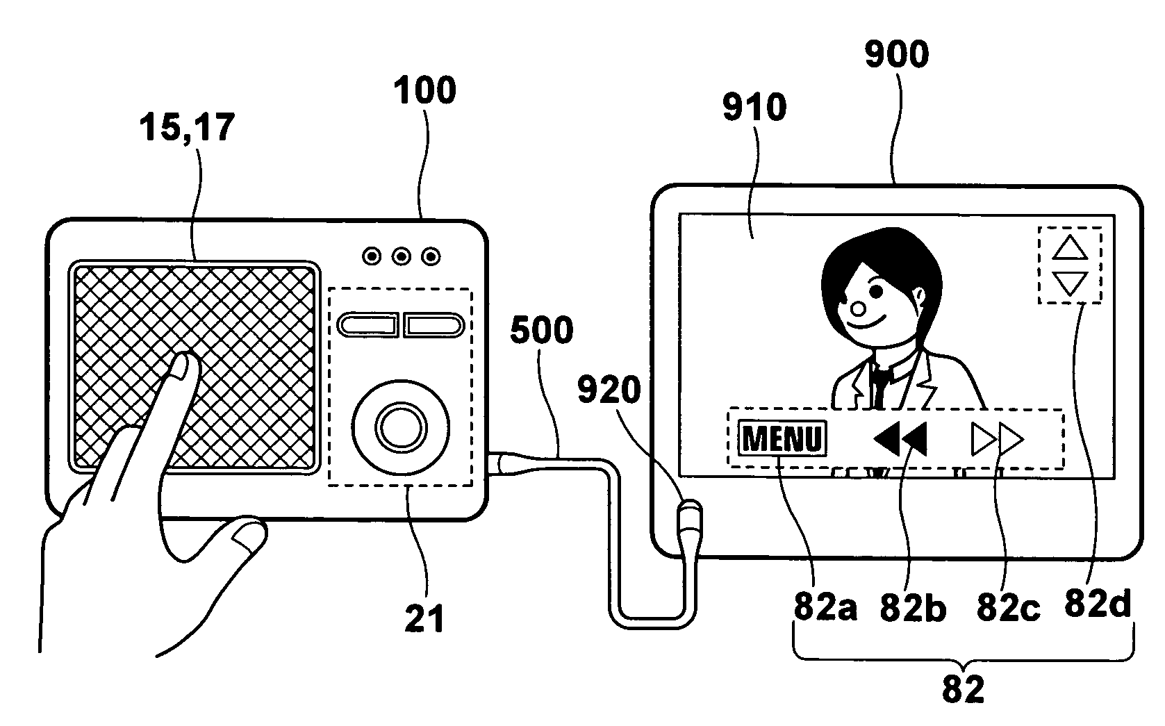
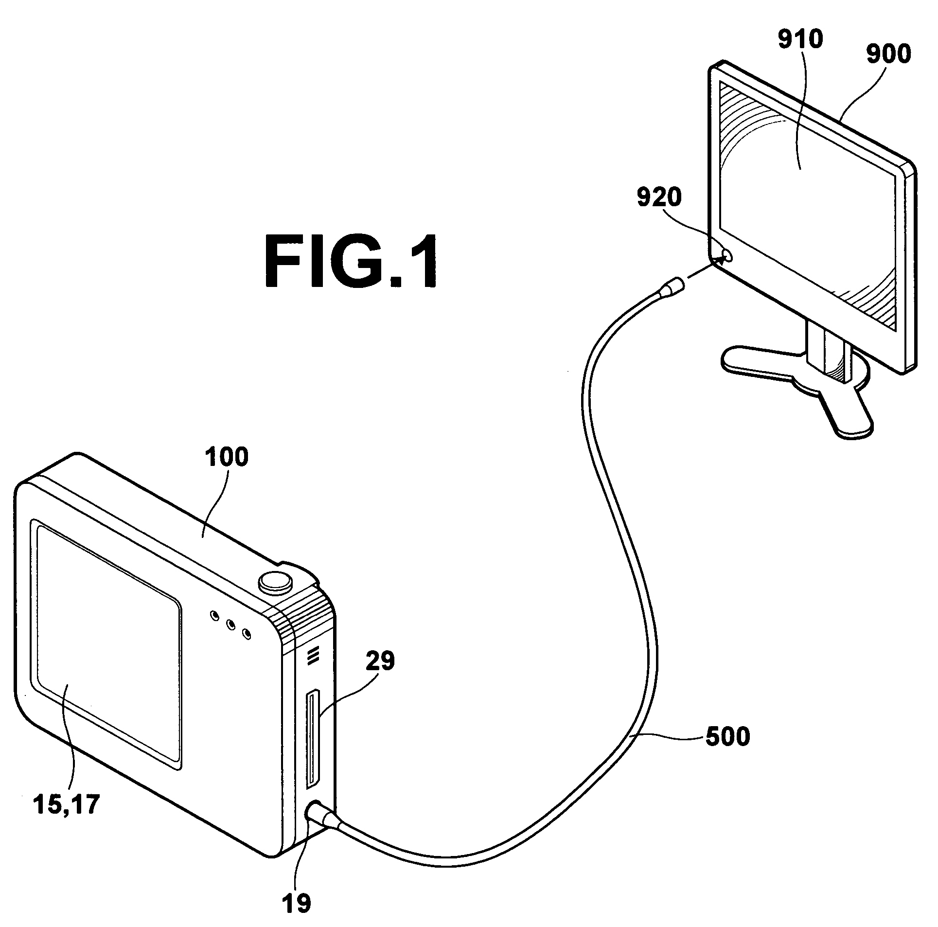
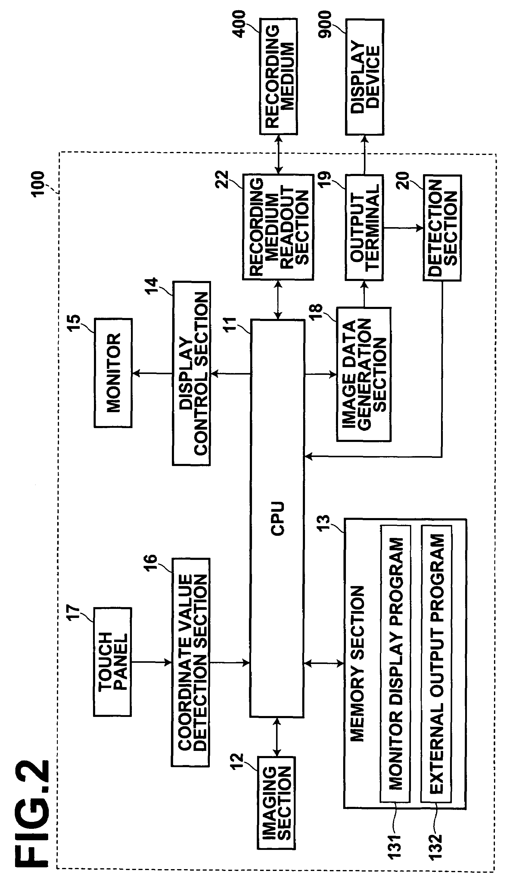
[0075]FIG. 1 is a drawing illustrating a rear perspective view of a digital camera 100 to which the present invention is applied, and a front view of a display device 900. Although not shown, the digital camera 100 includes functional elements generally required for imaging on the front side thereof, such as a lens, a strobe, an auxiliary lamp, various sensors, and the like. It further includes on the rear and lateral sides thereof a monitor (display screen) 15, a touch panel 17, an output terminal 19, media slot 29, and the like. The monitor 15 displays an image recorded on a memory card inserted in the media slot 29, a menu screen required for performing various settings, or visual view of image data obtained by a CCD (not shown) at the time of imaging. In addition, it displays various operation buttons for selecting / performing various functions, such as for giving an instruction to switch the display from normal screen to menu screen, giving an instruction to perform switching be...

second embodiment

[0100]Hereinafter, a second embodiment will be described. In the second embodiment, elements identical to those used in the first embodiment are given the same reference numerals and will not be elaborated upon further here.

[0101]FIG. 6 is a block diagram of a digital camera 100a according to the second embodiment, illustrating the internal configuration thereof. The digital camera 100a includes: the CPU 11; the imaging section 12; a memory section 30; the display control section 14; the monitor 15; the coordinate value detection section 16; the touch panel 17; the image data generation section 18; the output terminal 19; the detection section 20; and the recording medium readout section 22.

[0102]The memory section 30 has stored thereon a monitor display program 310 for displaying an image on the monitor 15, an external output program 320 for outputting image data to an external device, such as the display device 900, a slide operation / function table 330 in which types of slide oper...


PUM


Abstract

An image display apparatus that includes: a display screen having a touch panel function on which an image is displayed with operation buttons superimposed on the image, and a switching detection means for detecting a display switching operation for switching the display of the image from the display screen to an external device. When the display switching operation is detected by the switching detection means, the following is performed: the display of the image on the display screen is terminated and image data for displaying the image with the operation buttons superimposed on the image are outputted to the external device from the output terminal; the position information of a touched position on the display screen is detected; and one of the operation buttons displayed on the external device is selected according to the detected position information.

Description

BACKGROUND OF THE INVENTION[0001]1. Field of the Invention[0002]The present invention relates to an image display apparatus that includes a display screen having a touch panel function, and an image display method applied to the image display apparatus.[0003]2. Description of the Related Art[0004]Recently, the trend toward larger display screens has been in progress in electronic devices, such as digital cameras having display screens and the like, in order to improve their visibility of the images. On the other hand, reduction in the weight and size of the devices is also important. Consequently, development of such electronic devices as described, for example, in Japanese Unexamined Patent Publication Nos. 5(1993)-244592 and 11(1999)-164175, and U.S. Pat. No. 7,034,881 has been in progress. These electronic devices are equipped with a touch panel function on the display screen and the user operates the device in various ways through touch operation buttons displayed on the display...

Claims


Application Information

Patent Timeline
Patent Type & Authority Patents(United States)
IPC IPC(8): G06F3/041G06F3/038
CPCG06F3/0488
Inventor FUNAMOTO, KENJI
Owner FUJIFILM CORP
Learn More