
Universal adjustable spacer assembly

a technology of adjustable spacers and assembly parts, which is applied in the direction of auxillary members of forms/shuttering/falseworks, machine supports, furniture parts, etc., can solve the problems of forming ridges in wedges, lack of flexibility in performance or complexity in construction, and inability to make the most efficient use of force applied to wedges

Inactive Publication Date: 2010-04-27
SELNESS JERRY N
View PDF9 Cites 222 Cited by
  • Summary
  • Abstract
  • Description
  • Claims
  • Application Information

AI Technical Summary

Problems solved by technology

Various shortcomings of the prior art include lack of flexibility in performance or complexity in construction.
Mechanisms simply using two opposed wedges with forces applied to a threaded shaft parallel to long, flat surfaces of the wedges do not make the most efficient use of force applied to the wedges.
Forming ridges in wedges creates additional expense in manufacture.
Aspects of complexity of this apparatus include the requirement to have opposite ends of the bolt formed with a left hand thread and a right hand thread respectively.
These structures are not “universal” in application.

Method used


Image

  • Universal adjustable spacer assembly
  • Universal adjustable spacer assembly
  • Universal adjustable spacer assembly

Examples


Embodiment Construction

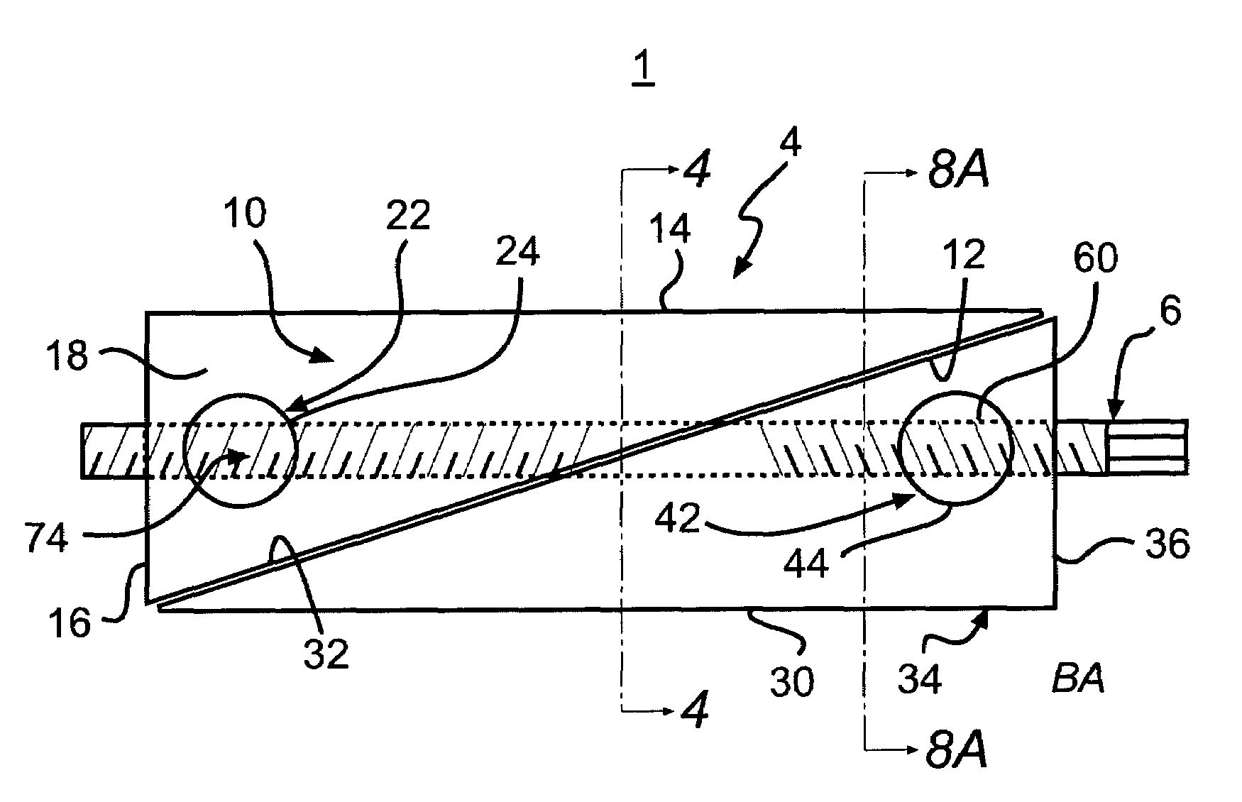
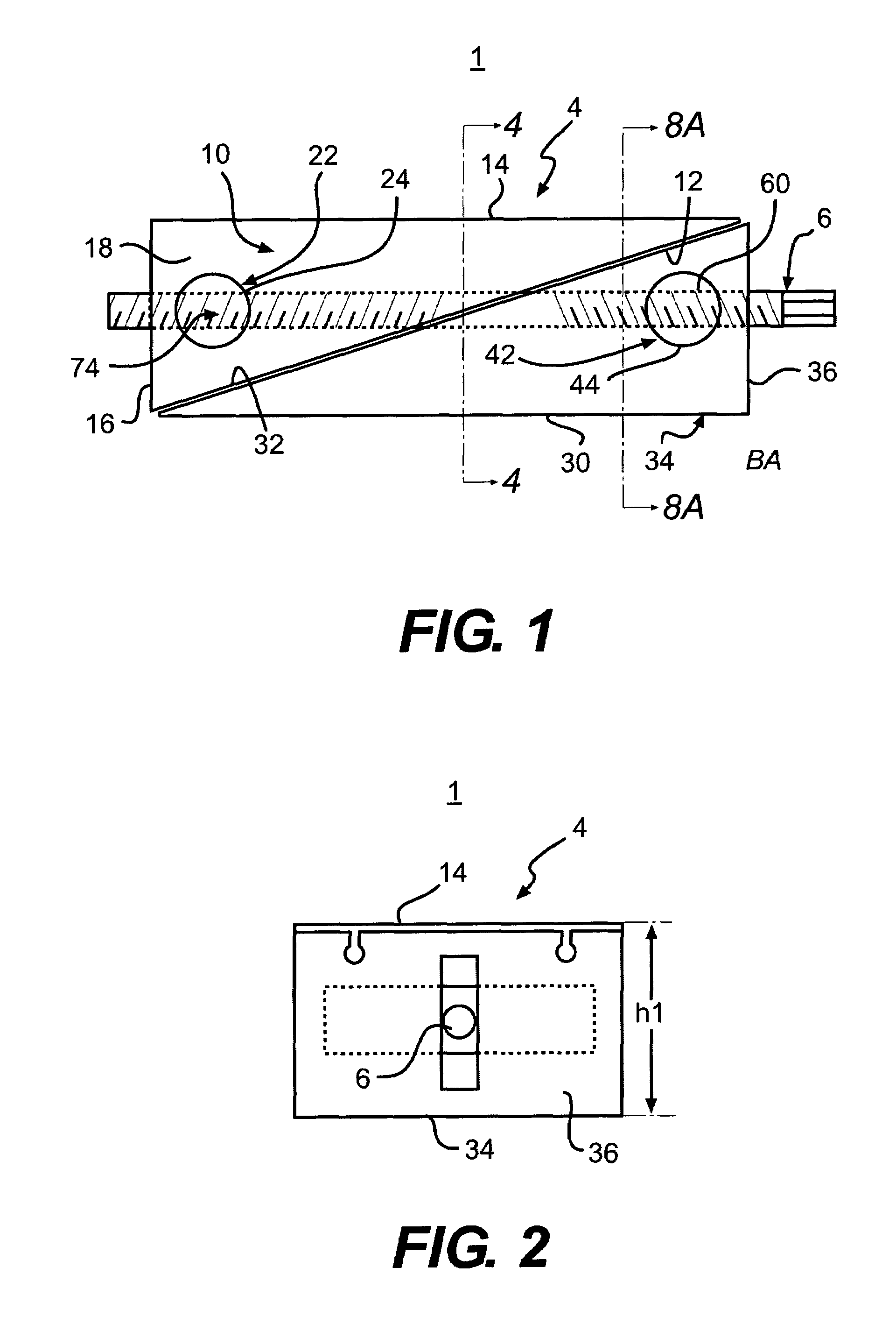
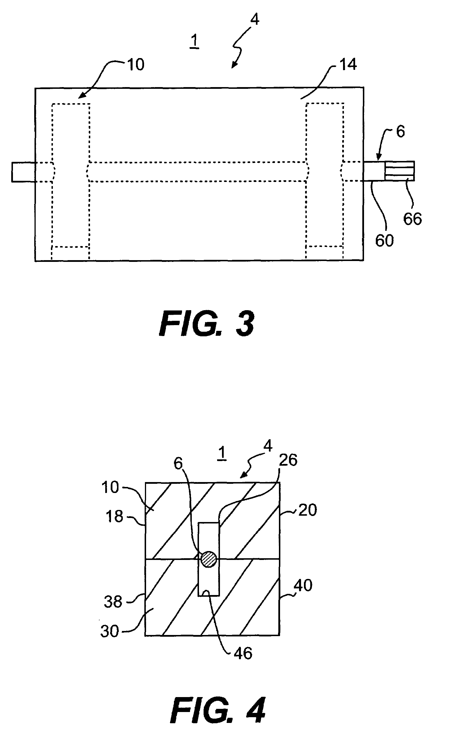
[0026]Embodiments of the present invention utilize an opposed wedge mechanism in which first and second wedges translate with respect to one another in a longitudinal dimension. As inclined faces of the wedges slide along each other, the vertical distance between an upper horizontal surface on the first wedge and a lower surface on the second wedge will increase or decrease, depending on the direction in which the translation takes place. Directions such as vertical, horizontal, transverse and longitudinal are used in the present description only in a relative sense in order to define orientation of components with respect to each other. Operation of the embodiments is not dependent on particular orientation of the spacer assembly.

[0027]A universal adjustable spacer assembly 1 comprises a wedge pair 4 and a semi-longitudinal connector 6. Turning the semi-longitudina1 connector 6, when threaded, translates wedges in the wedge pair 4 with respect to each other in a longitudinal direct...


PUM


Abstract

In a universal, adjustable spacer assembly, first and second opposed wedges have faces that are inclined with respect to a longitudinal axis. As the wedges translate along the longitudinal axis with respect to one another, vertical distance between an upper face and a lower face of the first and second wedges respectively changes. Longitudinally displaced portions of a rotatable member such as a threaded rod are received in a first and a second collar member pivotally mounted with respect to the first and second wedges respectively. As the rod rotates, longitudinal distance between the collar members changes, and the wedges slide against each other, the collar members rotate within each wedge. In a further form, opposing track members may be fixed to inclined surfaces of the first and second wedges respectively.

Description

CROSS-REFERENCE TO RELATED APPLICATIONS[0001]The present application claims priority to U.S. Provisional Patent Application Ser. No. 60 / 590,122 filed Jul. 21, 2004, the disclosure of which is incorporated herein by reference in its entirety.FIELD OF THE INVENTION[0002]The present subject matter relates to an adjustable spacer assembly.BACKGROUND OF THE INVENTION[0003]Adjustable spacer assemblies are used in many contexts. They may be used to fill space in order to secure an item against motion within a container. When a spacer is used, it may replace or supplement the use of packing material. Adjustable spacer assemblies may be used for furniture leveling. Adjustable spacer assemblies are used in orthopedic surgery in such applications spinal fusion to fill space between adjacent vertebrae surrounding a missing vertebra. Adjustable spacer assemblies may be used to set the height of a worktable or load-bearing surface.[0004]Various shortcomings of the prior art include lack of flexib...

Claims


Application Information

Patent Timeline
Patent Type & Authority Patents(United States)
IPC IPC(8): F16M11/00
CPCA47B91/028
Inventor SELNESS, JERRY N.
Owner SELNESS JERRY N
Learn More