
Intuitive ultrasonic imaging system and related method thereof

a technology of ultrasonic imaging and intuitiveness, applied in ultrasonic/sonic/infrasonic image/data processing, instruments, applications, etc., can solve the problems of high cost systems that are so complex as to require specialized technicians for operation, ultrasound is still very sophisticated and requires a well-trained operator

Active Publication Date: 2010-04-20
UNIV OF VIRGINIA ALUMNI PATENTS FOUND
View PDF18 Cites 124 Cited by
  • Summary
  • Abstract
  • Description
  • Claims
  • Application Information

AI Technical Summary

Problems solved by technology

Medical imaging is a field dominated by high cost systems that are so complex as to require specialized technicians for operation and the services of experienced medical doctors and nurses for image interpretation.
However it makes ultrasound impractical for many of the routine tasks for which it would be clinically useful.
While far less expensive than high-end systems, these systems are still very sophisticated and require a well-trained operator.
Furthermore, at this price few new applications are opened.
The applicability of conventional ultrasound is further limited by the typical image format used.
This image format is non-intuitive and the simple act or process of mentally registering the B-Mode image to the patients anatomy requires significant experience.
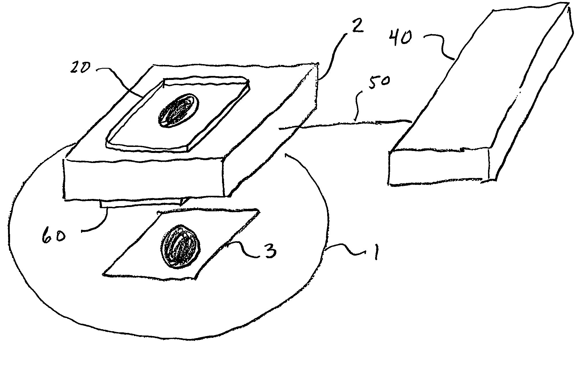
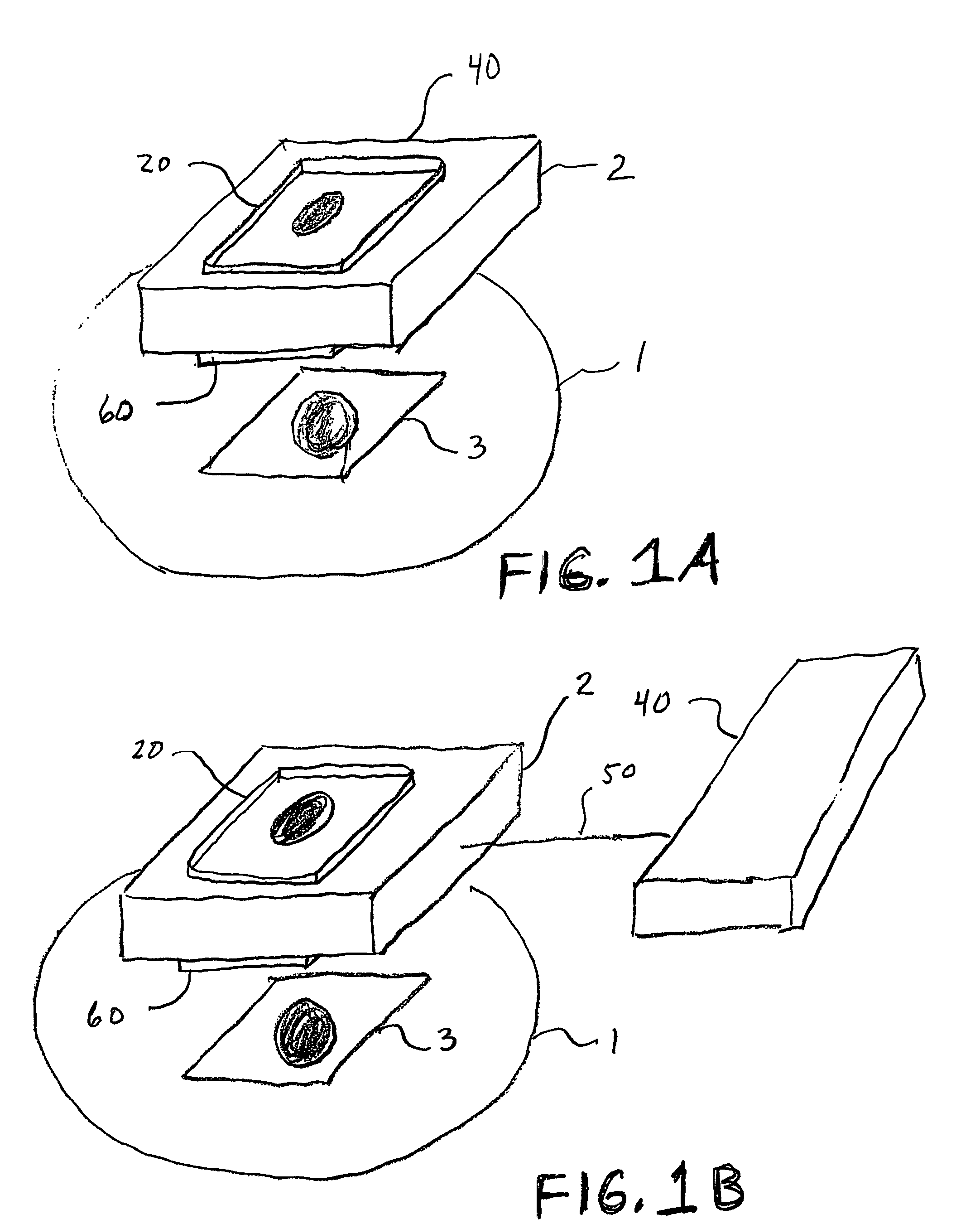
Unfortunately this configuration is not intuitive for most users because the image appears far from the patient.
Most new users find images in this format very difficult to interpret and to register mentally with the tissue geometry.
Conventional system configurations can be awkward to use because of the lengthy cable involved.
Finally, the typical large size of the beamformer limits the system's portability.
For example, but not limited thereto, Bunce '498 continues to use the confusing b-mode image format and its configuration is not intuitive for some users making it difficult for an untrained user to interpret the image and connect it to the organ, target, or subject under investigation.

Method used


Image

  • Intuitive ultrasonic imaging system and related method thereof
  • Intuitive ultrasonic imaging system and related method thereof
  • Intuitive ultrasonic imaging system and related method thereof

Examples


examples

[0054]The following example is intended for illustrative purposes only and is not intended to be limiting in any manner.

example no.1

Example No. 1

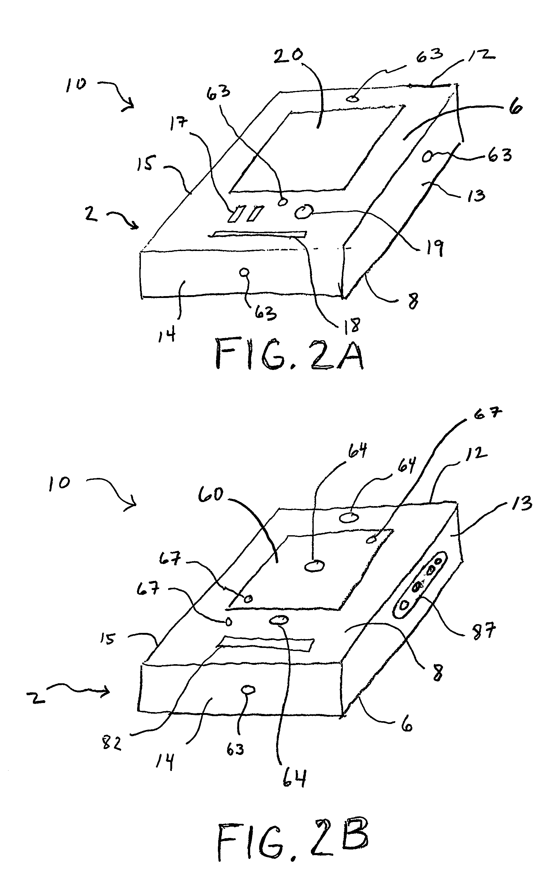
[0055]Referring to FIG. 7, a schematic block diagram of an embodiment of the invention is shown, whereby a two-dimensional piezoelectric transducer array 60 is utilized. The transducer array 60 consists of a 32×32 element array of 500×500 un elements 62. These elements can be constructed by using a commercially available wafer dicing saw to cut a Lead Zirconate Titanate (PZT) ceramic that had been mounted to a printed circuit board. While the printed circuit board does not provide optimal acoustic properties, it can be easily fabricated at a low cost. Selection of non-standard materials as the substrate for the printed circuit board (such as a thermoplastic) will enable some control over the acoustic response of the transducer. The printed circuit board provides the connection to one side of the elements 62. The other side of the elements is tied to a common ground plane by adhering a foil layer to the surface using an electrically conductive epoxy.

[0056]A transmit-rece...


PUM


Abstract

A hand held ultrasonic instrument (10) is provided in a portable unit that performs C-Mode imaging and collects 3D image data. In a preferred embodiment a transducer array (60), display unit (20), beamformer (40), power system, and image processor are integrated in one enclosure weighing less than three pounds. In operation, the portable unit is scanned across a target and the displayed image is conveniently presented to the operator whereby the displayed image corresponds exactly to the target, or a scaled fashion if desired.

Description

CROSS-REFERENCES TO RELATED APPLICATIONS[0001]This application is a national stage filing of International Application No. PCT / US03 / 06607, filed on Mar. 6, 2003, which claims benefit under 35 U.S.C Section 119(e) from U.S. Provisional Application Ser. No. 60 / 362,763, filed Mar. 8, 2002, entitled “An Intuitive Ultrasonic Imaging System and Related Method thereof,” the entire disclosures of which are hereby incorporated by reference herein in their entirety.FIELD OF THE INVENTION[0002]The present invention is directed to ultrasonic diagnostic systems and methods and, in particular, a substantially integrated hand held ultrasonic diagnostic instrument.BACKGROUND OF THE INVENTION[0003]Medical imaging is a field dominated by high cost systems that are so complex as to require specialized technicians for operation and the services of experienced medical doctors and nurses for image interpretation. Medical ultrasound, which is considered a low cost modality, utilizes imaging systems costin...

Claims


Application Information

Patent Timeline
Patent Type & Authority Patents(United States)
IPC IPC(8): A61B8/00A61B8/06A61B8/08G01S7/52G01S15/89
CPCG01S15/8979G01S15/8995G01S15/8925A61B8/0841A61B8/06G01S7/5208A61B8/483A61B5/418A61B8/13A61B8/462A61B8/0833G01S15/8993A61B8/4427G01S7/52061A61B5/415A61B8/4455A61B5/4818A61B2562/028A61B8/488G01S7/52038G01S7/52071A61B8/08A61B2017/3413A61B8/14A61B8/466A61B8/5215
Inventor WALKER, WILLIAM F.HOSSACK, JOHN A.BLALOCK, TRAVIS N.
Owner UNIV OF VIRGINIA ALUMNI PATENTS FOUND
Learn More