
Wiper blade package

a technology for wiper blades and packaging, applied in the field of packaging, can solve the problems of warped or distorted wiper blade ends, warped or distorted wiper blades being returned to the store for refund, etc., and achieve the effect of strengthening and structural rigidity of the packag

Inactive Publication Date: 2010-04-20
PORTAGE PLASTICS
View PDF51 Cites 38 Cited by
  • Summary
  • Abstract
  • Description
  • Claims
  • Application Information

AI Technical Summary

Benefits of technology

"The present invention is a package for a wiper blade that is pre-curved beam construction. The package has a tri-fold construction with a spine hingably attaching the package halves. Each package half has a seat that releasably receives one side or edge of the beam of the blade. The package halves include stiffening ribs that help strengthen and structurally rigidify the package when closed. The package is aesthetically attractive, durable, lightweight, and easy to make and use. It is more versatile and adaptable than other packages."

Problems solved by technology

Packaging such a beam-type windshield wiper blade poses unique challenges as compared to conventional wiper blades because of its curved beam.
One challenge relates to the fact that beam-type wiper blades are significantly wider than conventional wiper blades.
Another challenge relates to protecting the wiper element.
Due to the curvature of the beam and the arrangement of the wiper element, the end of the wiper element can become warped or distorted over time if the blade is not properly supported.
This can cause that part of the wiper element to make poor contact with the windshield, which can cause undesirable streaking during wiper operation.
This warpage or distortion can also extend along part of the squeegee edge of the wiper element, making these problems even worse.
If too great, it can undesirably result in such warped or distorted wiper blades being returned to the store for refund.

Method used


Image

  • Wiper blade package
  • Wiper blade package
  • Wiper blade package

Examples


Embodiment Construction

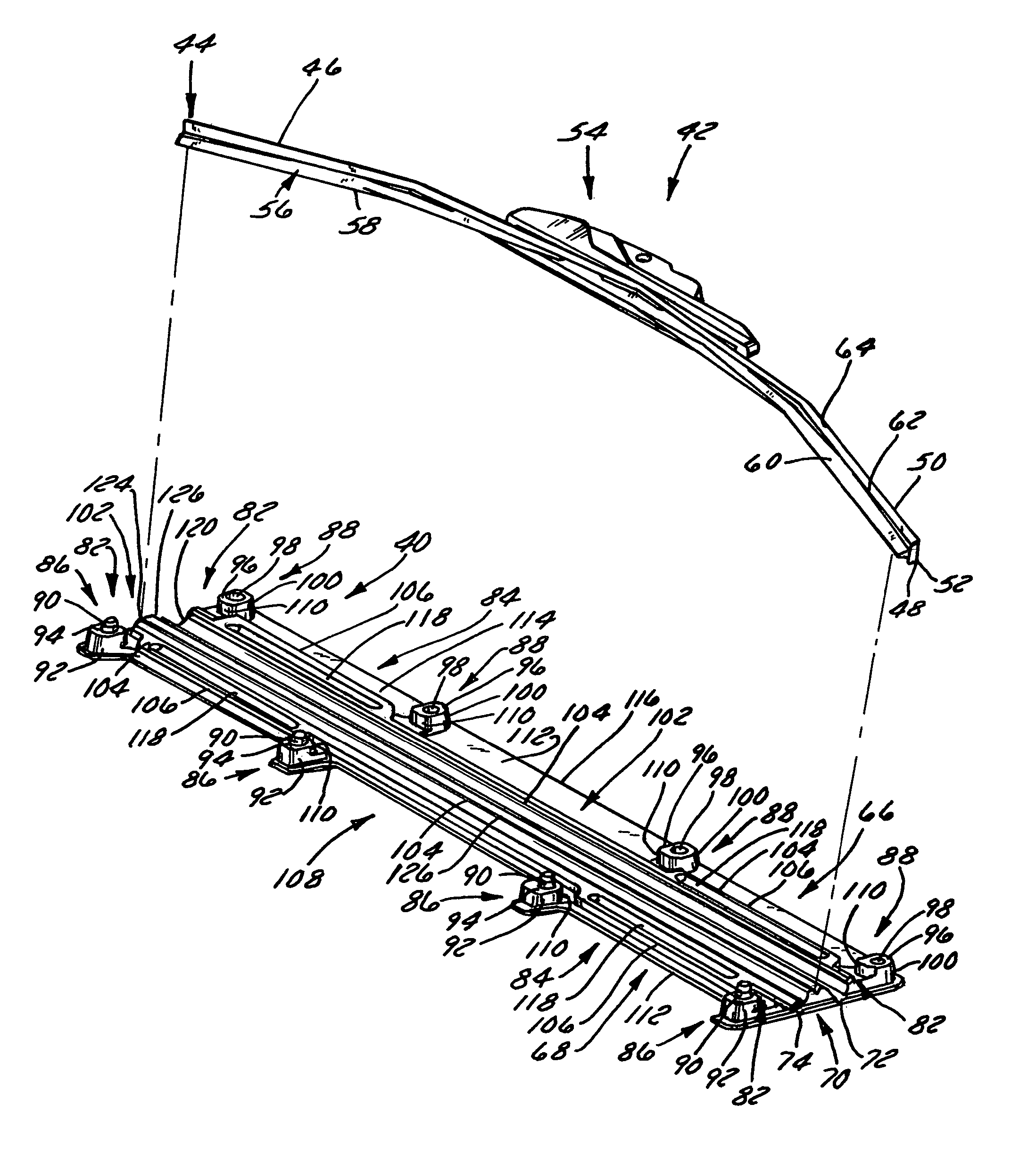
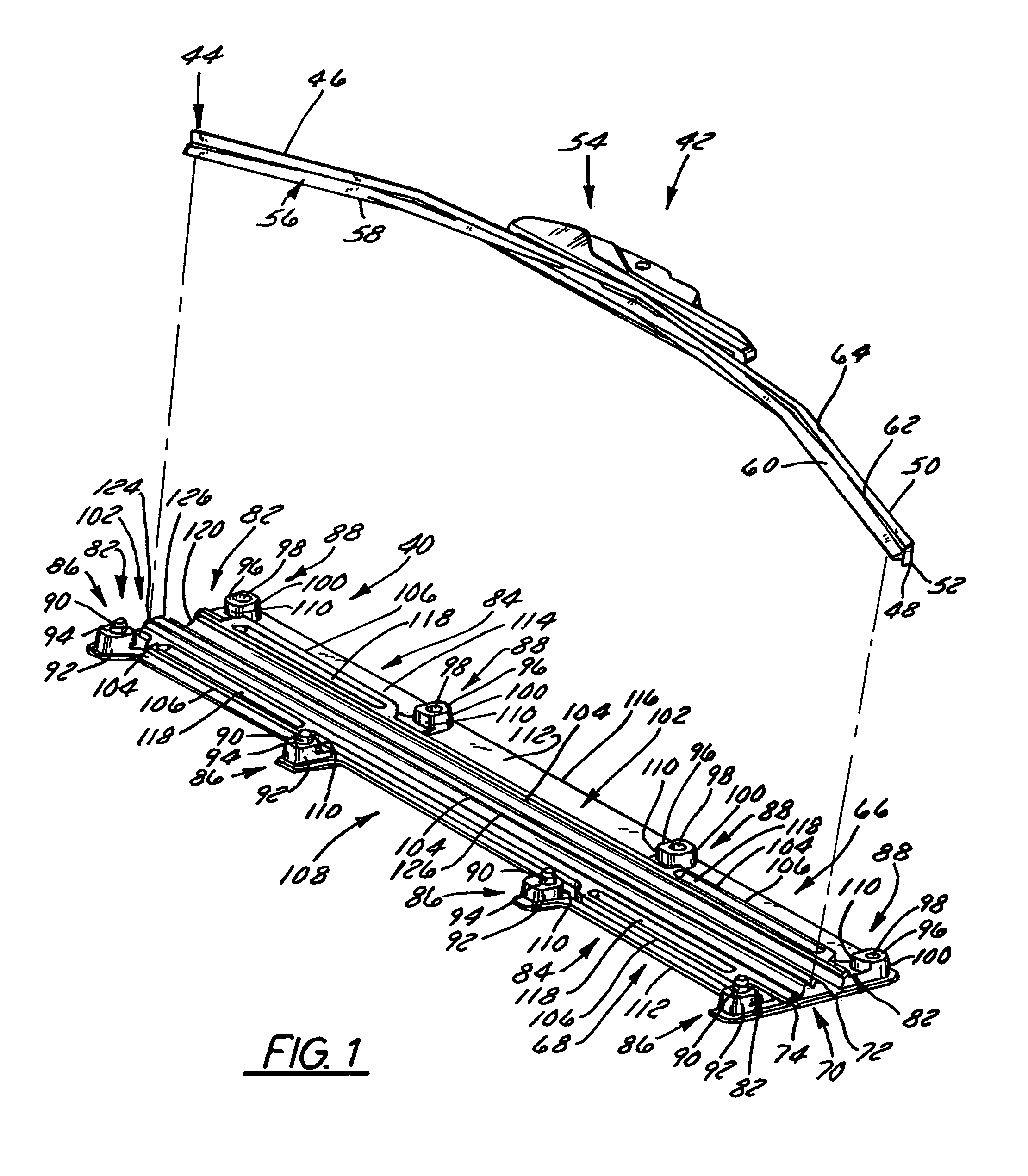
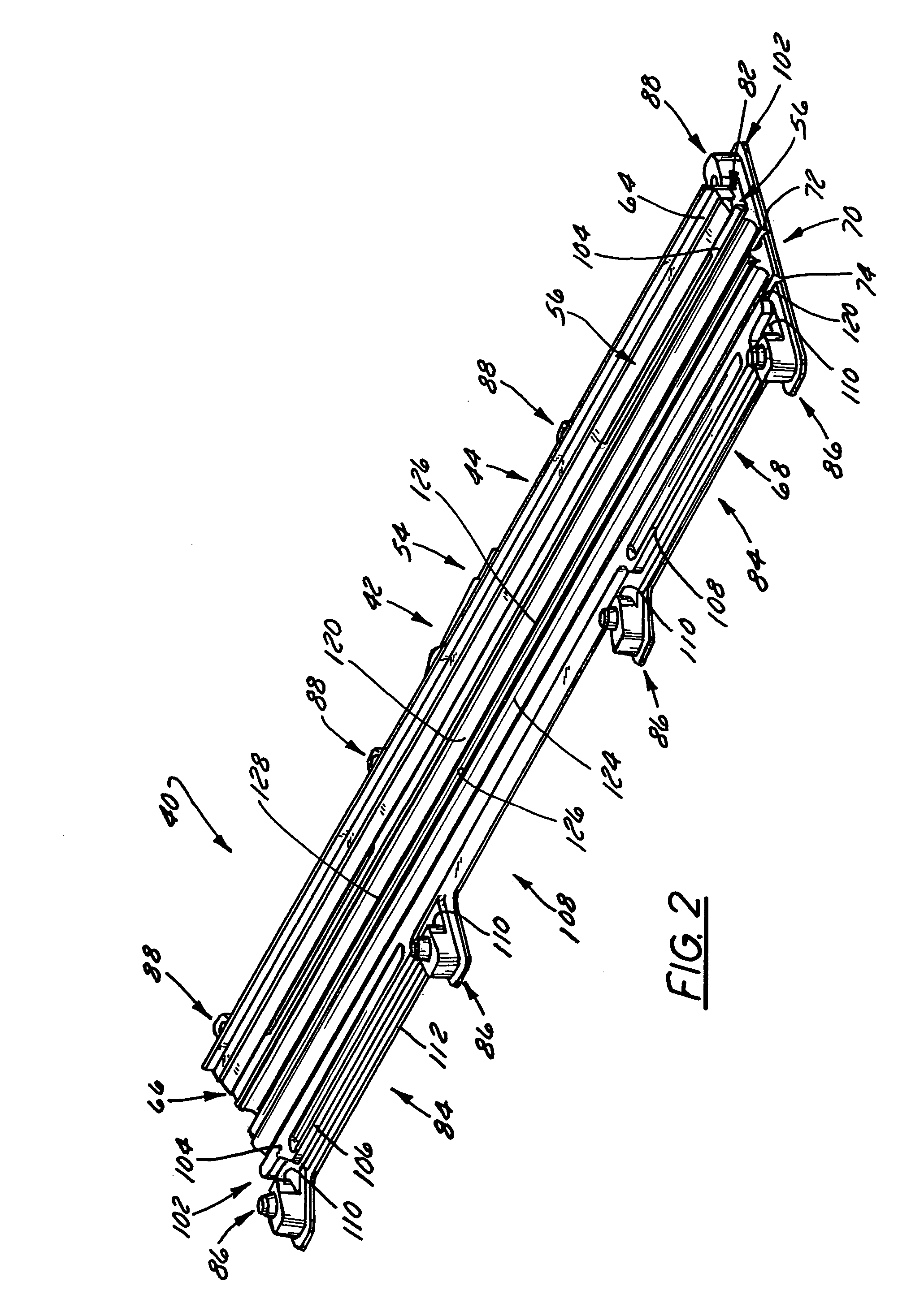
[0028]FIG. 1 illustrates a preferred embodiment of a package 40 for a curved beam-type wiper blade 42 that is constructed and arranged to receive and releasably retain the blade 42. The package 40 is configured to retain the beam-type wiper blade 42 in at least a partially straightened condition while also protecting it. The package 40 preferably is constructed and arranged to be reclosable and to releasably retain the beam-type wiper blade 42 in a straightened condition without contacting any portion of its rubber-like wiper element 56.

[0029]The exemplary beam-type wiper blade 42 depicted in FIG. 1 has a beam 44, also referred to as a backbone, that is curved such that it has at least one radius of curvature. The beam 44 is generally rectangular in cross section and has a pair of outer surfaces 46, 48 and a pair of side edges 50 and 52. The beam 44 is formed or pre-formed so as to be curved, such as in the manner shown in FIG. 1. Typically, the beam 44 is made of steel, such as spr...


PUM

PropertyMeasurementUnit
transverse widthaaaaaaaaaa
thicknessaaaaaaaaaa

Abstract

An elongate article holding package for a wiper blade having a pair of package panels with at least one of the panels including a blade beam receiving seat and a support flat upon which part of the blade rests during packaging. When closed, the flats position and can clamp the blade therebetween. In a preferred embodiment, both panels are so configured and preferably include one or more longitudinal stiffeners that oppose bending moments created by force transmitted to the package by the blade beam. The package preferably is of tri-fold construction having a spine that is spaced from and protects the wiper element. The spine preferably includes at least a plurality of spaced apart longitudinally extending stiffeners. One or more stiffening flanges preferably are also provided. When closed, the panels and spine advantageously cooperate with each other to increase package crush and bending resistance.

Description

CROSS-REFERENCE TO RELATED APPLICATION[0001]This application claims all benefits from and priority to under 35 U.S.C. Section 119(e) to U.S Provisional Application Ser. No. 60 / 567,748, filed May 3, 2004, and to U.S Provisional Application Ser. No. 60 / 587,392, filed Jul. 13, 2004, the entirety of both of which are hereby expressly incorporated herein by reference.FIELD OF THE INVENTION[0002]The present invention relates to packaging and more particularly to wiper blade packaging that is particularly well suited for holding a beam-type vehicle wiper blade, particularly those of pre-curved beam construction.BACKGROUND OF THE INVENTION[0003]Beam-type windshield or windscreen wiper blades are growing in popularity throughout the United States and the world. Beam-type wiper blades have an elongate beam “backbone” that is curved along its length. They also have a rubber wiper element attached to one side of the beam and an adapter, used for releasably mounting the wiper blade to a vehicle,...

Claims


Application Information

Patent Timeline
Patent Type & Authority Patents(United States)
IPC IPC(8): B65D73/00B65D69/00B65D75/22B65D85/68
CPCB65D75/225B60S2001/3898B65D2585/6885B65D2585/6882
Inventor LEWIS, GREGG S.
Owner PORTAGE PLASTICS
Learn More