
Die and method of manufacturing cast product

a technology of die and casting, applied in the field of die and casting products, can solve the problems defective castings, mold cavities, etc., and achieve the effect of reducing the risk of molten metal wrinkles, incomplete filling, and reducing the risk of mold cavities

Inactive Publication Date: 2010-03-30
KK TOSHIBA
View PDF8 Cites 34 Cited by
  • Summary
  • Abstract
  • Description
  • Claims
  • Application Information

AI Technical Summary

Benefits of technology

[0011]A general architecture that implements the various feature of the invention will now be described with reference to the drawings. The drawings and the associated descriptions are provided to illustrate embodiments of the invention and not to limit the scope of the invention.

Problems solved by technology

Since the solidification time of the molten metal of, for example, a magnesium alloy is very short, the die-casting die of which the cross-sectional flow area (i.e., cross-sectional area of a space into which the molten metal is to be poured) is small may possibly fail to fill the molten metal into every corner of the product section, thereby causing insufficient filling.
Therefore, some die-casting dies that are liable to insufficient filling are provided with sub-runners and sub-gates that laterally support the flow in the product section, in addition to the main runner and the main gate.
In this process, the inventor found that air in one such thin-wall casting die was easily left between molten metal introduced through a main gate and molten metal introduced through sub-gates, and that defective casting, involving mold cavities, incomplete filling, or molten metal wrinkles, was liable to occur.
Since the die described in Jpn. Pat. Appln. KOKAI Publication No. 2003-48047 is provided with the sub-gates that surround the product section, air is easily left in the product section, so that it is difficult to reduce defective casting in this die.

Method used


Image

  • Die and method of manufacturing cast product
  • Die and method of manufacturing cast product
  • Die and method of manufacturing cast product

Examples


first embodiment

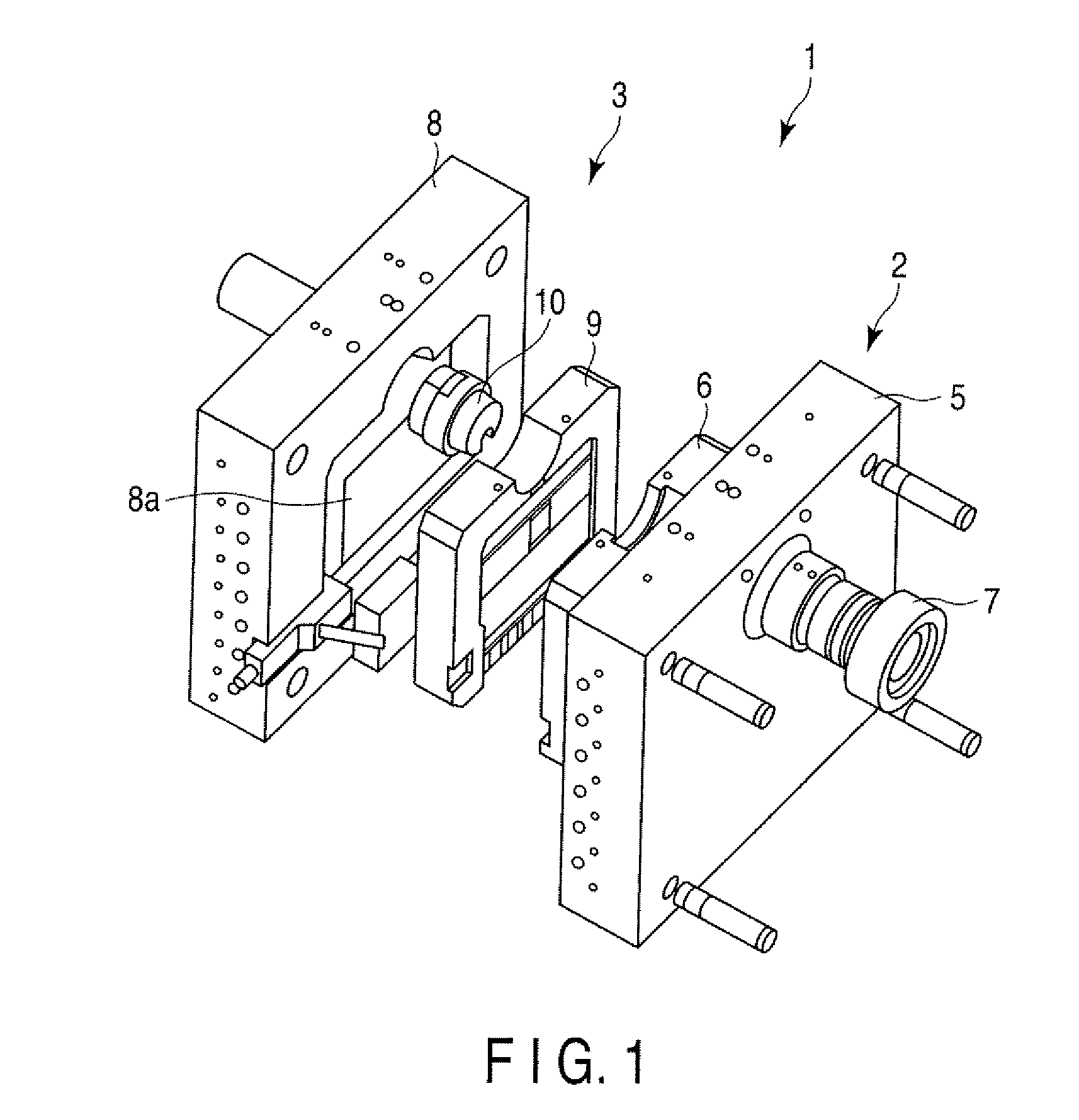
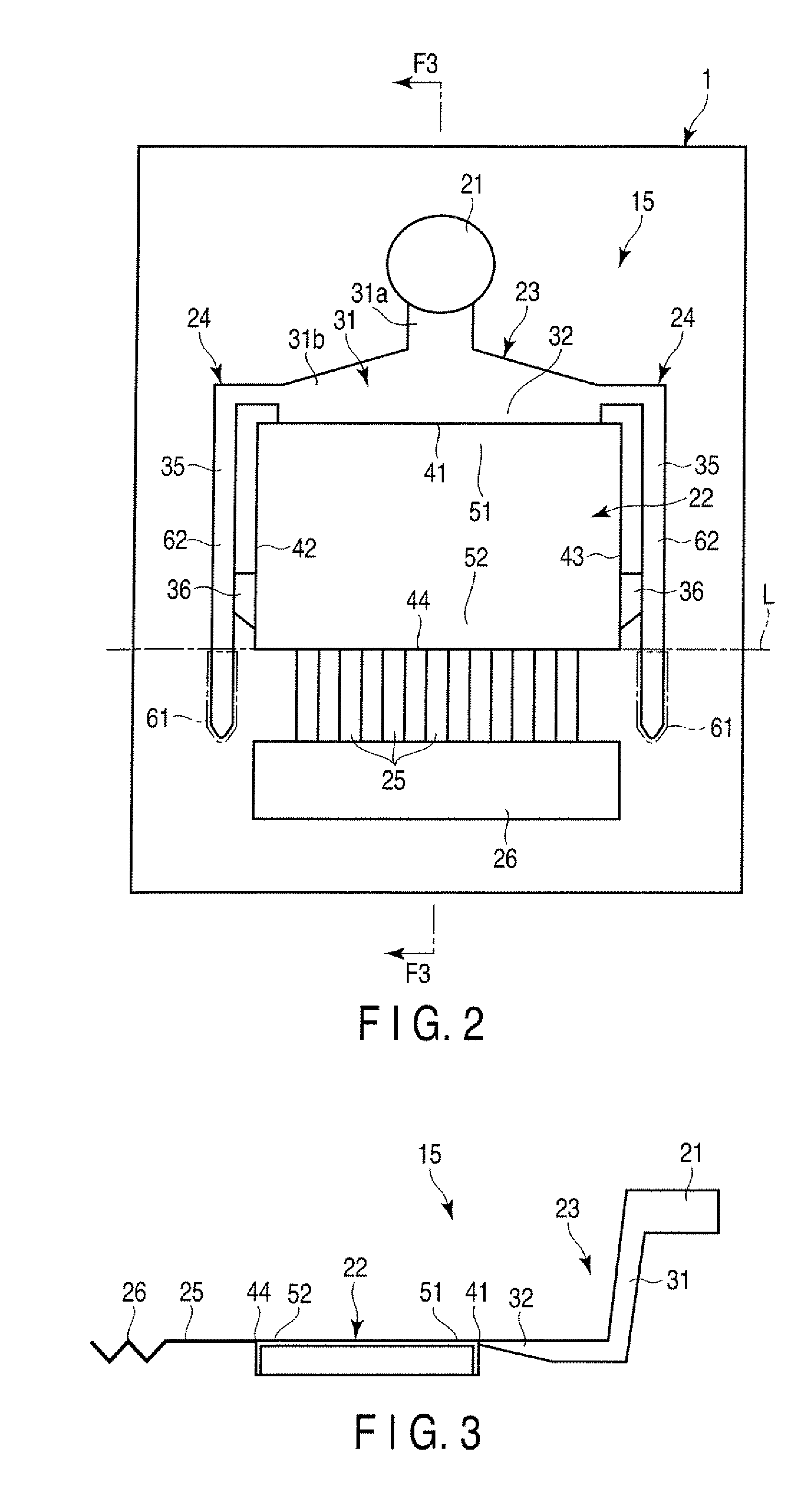
[0022]First, a die 1 and a method of manufacturing a cast product according to a first embodiment of the present invention will be described with reference to FIGS. 1 to 4.

[0023]FIG. 1 shows the die 1 according to the present embodiment. The die 1 is used for cold-chamber die casting, for example. Molten metal, such as a magnesium alloy, aluminum alloy, or zinc alloy, is poured into the die 1 under pressure. The die according to the present invention is not limited to those materials, and various materials may be widely used as the molten metal for die casing.

[0024]A cast product manufactured by using the die 1 is a component that forms a part of a housing of an electronic apparatus, such as a portable computer. The cast product of this type is a box-like structure that is provided with a bottom wall having, for example, a rectangular shape, and a standing wall rising from the peripheral edge portion of the bottom wall, and is open on one side. The cast product to which the present ...

second embodiment

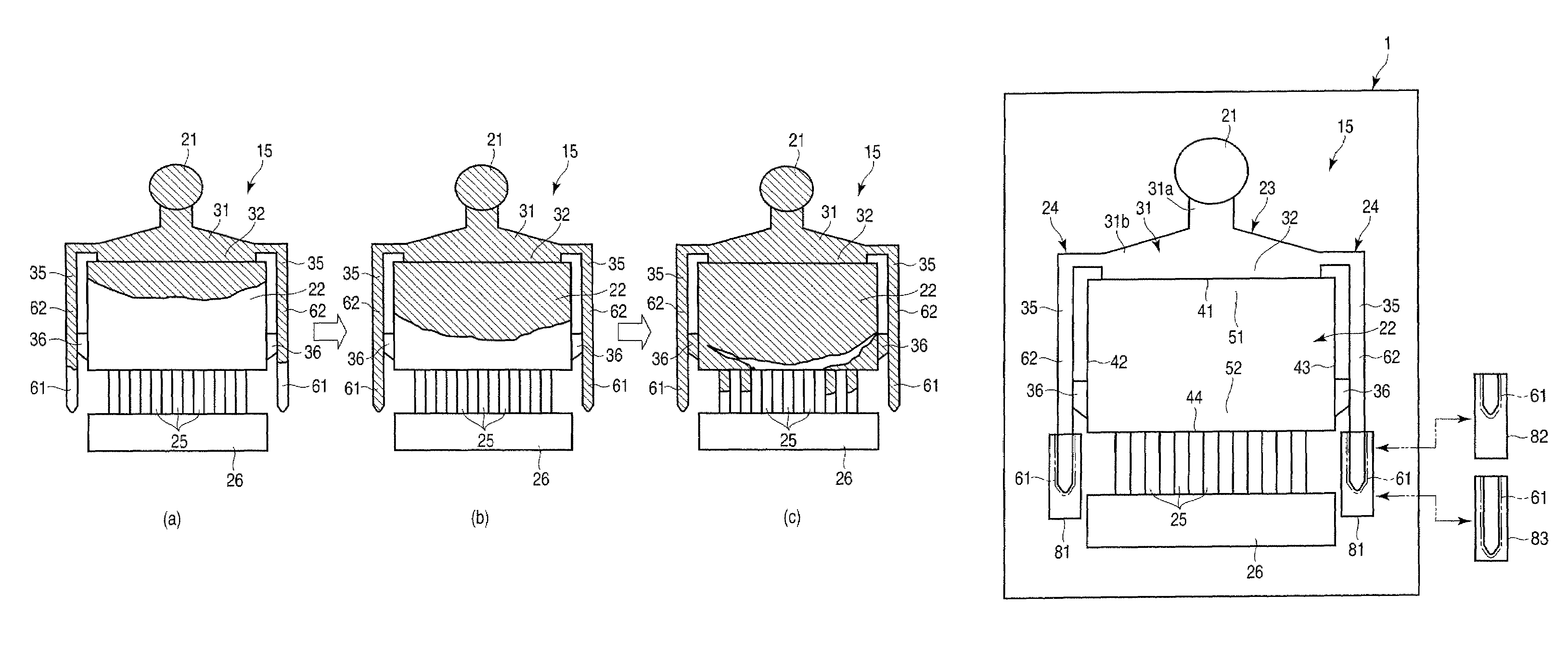
[0073]A die 1 and a method of manufacturing a cast product according to a second embodiment of the present invention will now be described with reference to FIG. 5. Like numbers are used to designate configurations with like or similar functions to those of the configurations of the first embodiment, and a description of those configurations is omitted.

[0074]In the die 1 according to the present embodiment, as shown in FIG. 5, a molten metal head 71 is provided on the distal end portion of an extension part 61 of each of sub-runners 35. The molten metal heads 71 are spaces defined in the die 1 and are filled with a molten metal that flows through the sub-runners 35 in a filling process. The heads 71 serve to increase the filling volumes of the sub-runners 35. Each head 71 is not limited to a specific shape and may be of any of various shapes, such as a circular or box-like shape. For other arrangements, the die 1 and the cast product manufacturing method of the present embodiment ar...

third embodiment

[0077]A die 1 and a method of manufacturing a cast product according to a third embodiment of the present invention will now be described with reference to FIG. 6. Like numbers are used to designate configurations with like or similar functions to those of the configurations of the first embodiment, and a description of those configurations is omitted.

[0078]In the die 1 according to the present embodiment, as shown in FIG. 6, an extension part 61 of each of sub-runners 35 has a telescopic structure. Specifically, a region Including the extension part 61 is unitized as a liner 81 (i.e., a replaceable piece) for the die 1, and the liner 81 is replaceable with another liner 82 or 83 that forms a sub-runner 35 of a different shape (ex., a different length). Thus, the filling volume of each sub-runner 35 can be changed by replacing the liner 81 with the alternative liner 82 or 83. For other arrangements, the die 1 and the cast product manufacturing method of the present embodiment are th...


PUM

PropertyMeasurementUnit
thicknessaaaaaaaaaa
thicknessaaaaaaaaaa
sizeaaaaaaaaaa

Abstract

According to one embodiment, a die is provided with a stationary die and a movable die. When the movable die is combined with the stationary die, a biscuit section, a product section in which a product is to be cast, a main runner configured to guide a molten metal from the biscuit section toward the product section, a main gate provided between the main runner and the product section, a sub-runner diverging from the main runner and extending along a side edge part of the product section, and a sub-gate provided between the sub-runner and the product section are formed between the stationary die and the movable die. The sub-gate is connected to the side edge part in an end portion of the product section. The sub-runner extends beyond the product section in a direction in which the side edge part extends.

Description

CROSS-REFERENCE TO RELATED APPLICATIONS[0001]This application is based upon and claims the benefit of priority from Japanese Patent Application No. 2008-020946, filed Jan. 31, 2008, the entire contents of which are incorporated herein by reference.BACKGROUND[0002]1. Field[0003]One embodiment of the present invention relates to a technique associated with die casing.[0004]2. Description of the Related Art[0005]A cold-chamber die-casting die is provided with a biscuit section, product section, main runner, and main gate. The biscuit section receives a molten metal from an injection apparatus of a casting machine. The product section is a space in which a product is to be cast. The main runner guides the molten metal from the biscuit section toward the product section. The main gate is provided between the main runner and the product section and has a sharply reduced thickness such that the flow (i.e., stream) of the molten metal can be accelerated.[0006]Since the solidification time o...

Claims


Application Information

Patent Timeline
Patent Type & Authority Patents(United States)
IPC IPC(8): B22D17/08B22D17/22
CPCB22D17/22B22D17/2272
Inventor HIRAO, HIROAKI
Owner KK TOSHIBA
Learn More