
Quick release camming mechanism

a camming mechanism and quick release technology, applied in the direction of release mechanisms, cycle equipment, rod connections, etc., can solve problems such as conventional forces, and achieve the effect of less tension and less for

Active Publication Date: 2010-02-23
CRANK BROS INC
View PDF11 Cites 25 Cited by
  • Summary
  • Abstract
  • Description
  • Claims
  • Application Information

AI Technical Summary

Benefits of technology

[0011]The present invention comprises a quick release mechanism that can be applied, among other things, to both skewers and to seat post clamps. By using two levers according to this novel invention, a quick release skewer is substantially easier to open and close. Similarly, the present invention is also applied to a quick release seat post clamp that is substantially easier to open and close. In each case, the quick release has two levers to open and close instead of one. Each lever requires about half the force of a conventional quick release lever to open and close. Or, with a conventional force applied to each lever, the clamping force is about double. A similar quick release camming mechanism can also be applied to many other products that use a quick release such as a tripod, a ski boot buckle, a patio umbrella, a folding bicycle or stroller, a SCUBA tank strap buckle, fitness equipment, etc.
[0012]When the first lever is pivoted closed, the cam of that lever applies a load off-center of the loaded shaft. This causes less tension to be applied to the shaft, which results in less force required. Then, when the second lever is pivoted closed, the cam of that lever applies the rest of the tensile load to the shaft.
[0013]If the user so chooses, they can open or close both levers simultaneously, resulting in conventional forces. In this way a person with strong hands could choose to open and close the quick release levers simultaneously, while a person with weaker hands could choose to open and close the levers one at a time.
[0015]Accordingly, it is an object of the present invention to provide a quick-release camming mechanism that allows a quick release skewer and / or a seat post clamp to have two levers for opening and closing. The two levers can either be opened or closed independently, each at a reduced force, or simultaneously at a conventional force.

Problems solved by technology

If the user so chooses, they can open or close both levers simultaneously, resulting in conventional forces.

Method used


Image

  • Quick release camming mechanism
  • Quick release camming mechanism
  • Quick release camming mechanism

Examples


Embodiment Construction

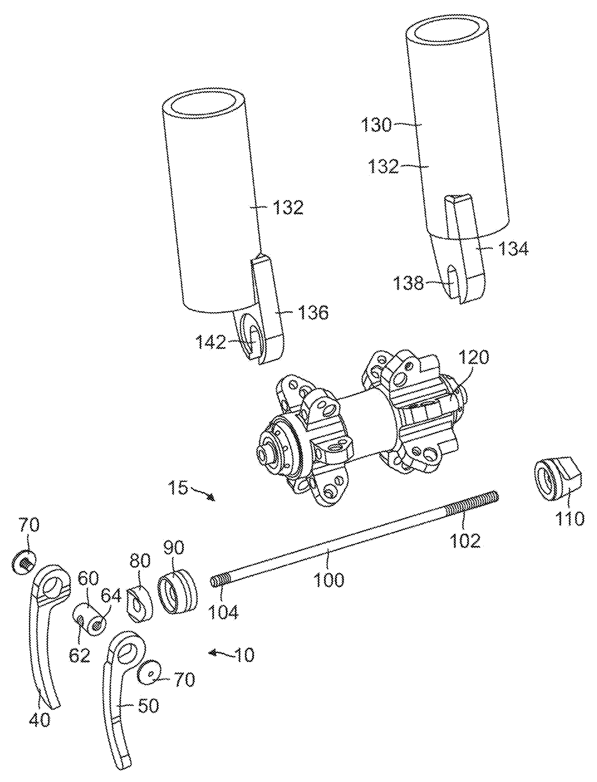
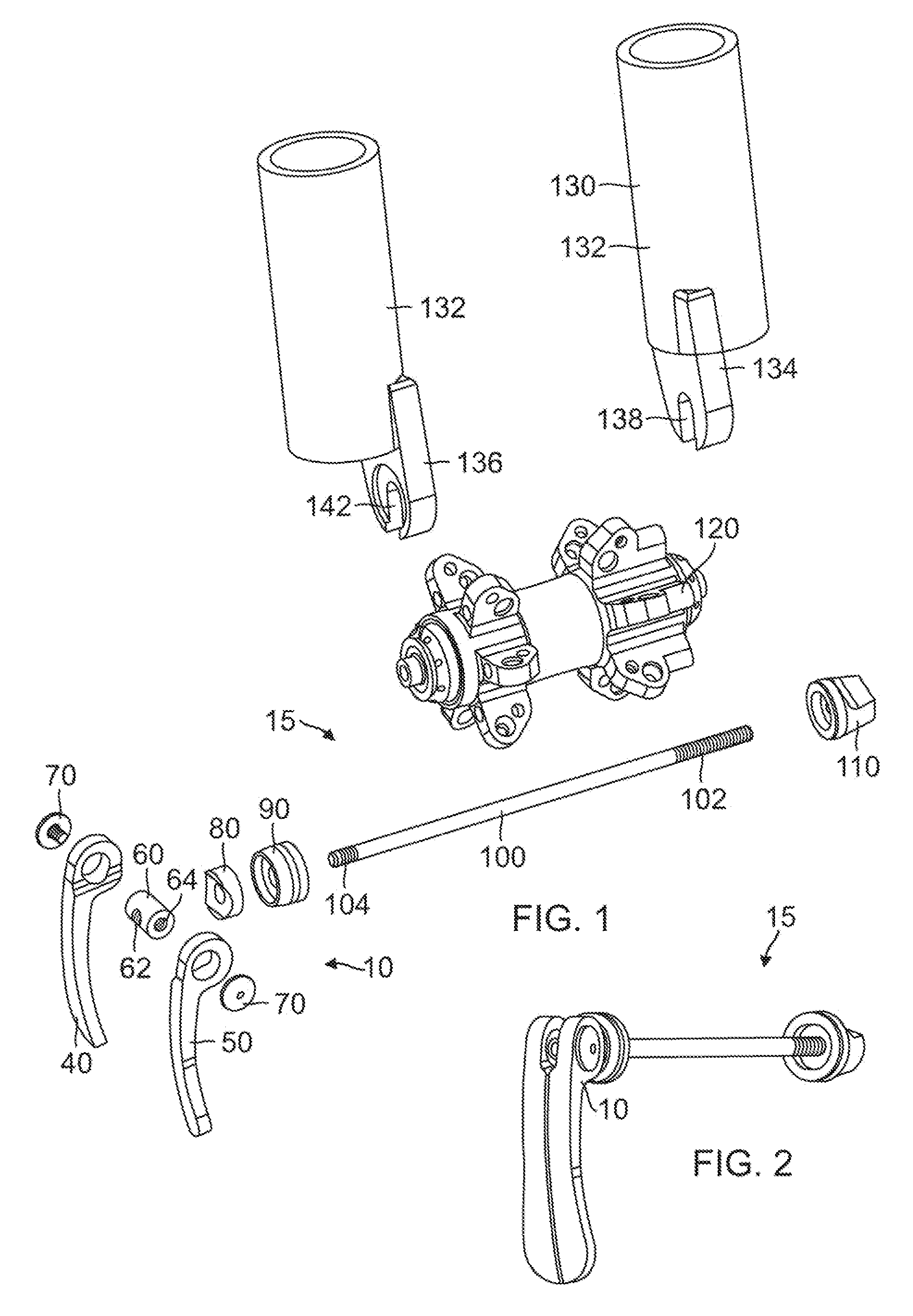
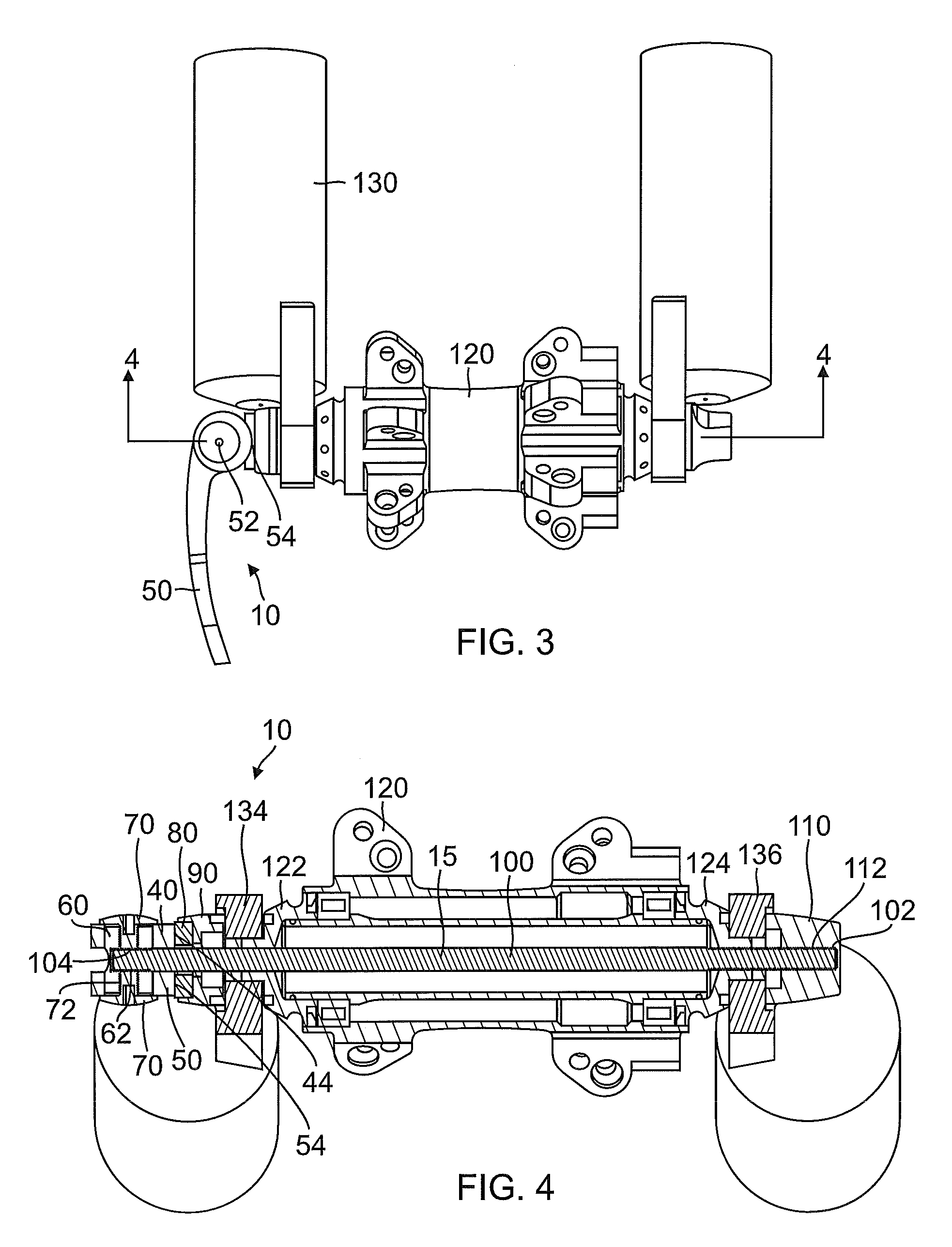
[0048]The present invention may be understood by referring to FIGS. 1-29. Referring first to FIGS. 1 to 11, it will be seen that the foregoing and other objects are attained, according to the present invention by a quick release camming mechanism 10 used in a bicycle quick release skewer 15 which is comprised of a shaft 100, an end cap 110, levers 40 and 50, two screws 70, a pin 60, a liner 80, and a cup 90. Skewer 15 secures a hub 120 to a fork 130. Whereas prior art quick release skewers have only a single lever, this novel skewer 15 has two independent levers. About half the force is required to independently push either lever 40 or 50 closed as is required to push both levers closed simultaneously. Similarly, about half the force is required to open either lever individually as is required to open them simultaneously. This is because about half the shaft 100 tensile load and about half of the friction is applied when one lever 40 or 50 is opened individually, compared to opening...


PUM


Abstract

A quick release camming mechanism is used in a bicycle skewer that secures a hub to a fork. Whereas prior art quick release mechanisms have only a single lever, this mechanism has two independent levers. About half the force is required to independently push either lever closed as to push both levers closed simultaneously. Similarly, about half the force is required to open either lever individually as to open them simultaneously. A similar quick release camming mechanism also works well for a quick release seat post clamp with similar advantages. The present invention is not limited to use on bicycle components.

Description

BACKGROUND OF THE INVENTION[0001]1. Field of the Invention[0002]The present invention relates to quick release camming mechanisms such as for retaining a bicycle wheel hub to the front fork and rear drop-out of a bicycle, to retaining a seat post to the seat tube of a bicycle frame, and, more particularly, to quick release devices that can be difficult to open or close.[0003]2. Background Art[0004]Quick-release skewers are well-known and are used on the wheels and frames of better quality bicycles to facilitate their mounting on or removal from the bicycle frame. Quick release skewers use a quick release camming mechanism. Typically, a quick-release skewer comprises a shaft having threaded ends, a large nut on one end, and a camming mechanism on the other end. The hub engages the drop-out slots of a front fork or rear stays (of the frame) immediately inboard of the nut and camming mechanism, so that actuation of the camming mechanism causes the drop-outs to be clamped against the wh...

Claims


Application Information

Patent Timeline
Patent Type & Authority Patents(United States)
IPC IPC(8): B60B35/00B62K25/02
CPCB60B27/026B62K25/02B62K2206/00Y10T403/68Y10T74/20792Y10T403/595Y10T74/2039Y10S403/08
Inventor WINEFORDNER, CARLHERMANSEN, FRANK
Owner CRANK BROS INC
Learn More