
Directional control of an automatic pool cleaner

a technology of automatic cleaning and directional control, which is applied in the direction of adjustable joints, pipe elements, applications, etc., can solve the problems of many of these pool cleaners not working satisfactorily in aboveground pools or in-ground pools, and the operation of the pool cleaner is no longer automati

Inactive Publication Date: 2010-02-02
ARENGO 309
View PDF20 Cites 3 Cited by
  • Summary
  • Abstract
  • Description
  • Claims
  • Application Information

AI Technical Summary

Benefits of technology

"The invention is a control system for a submerged surface suction cleaning apparatus that includes an elbow joint with swivels at each end. The swivels have anti-friction surfaces and the angle between the ends of the elbow joint is between 135° and 165° degrees. The elbow joint has friction spigot or socket connections at the inlet and outlet ends. The technical effect of this invention is to provide a more efficient and effective control system for submerged surface suction cleaning apparatus."

Problems solved by technology

Many of these pool cleaners do not work satisfactorily in aboveground pools or in-ground pools having the bottom and sidewalls of the pool meeting at substantially right angles.
This is not a satisfactory solution in that the directional control is insufficient to result in effective cleaning and the operation of the pool cleaner is no longer automatic.

Method used


Image

  • Directional control of an automatic pool cleaner
  • Directional control of an automatic pool cleaner

Examples


Embodiment Construction

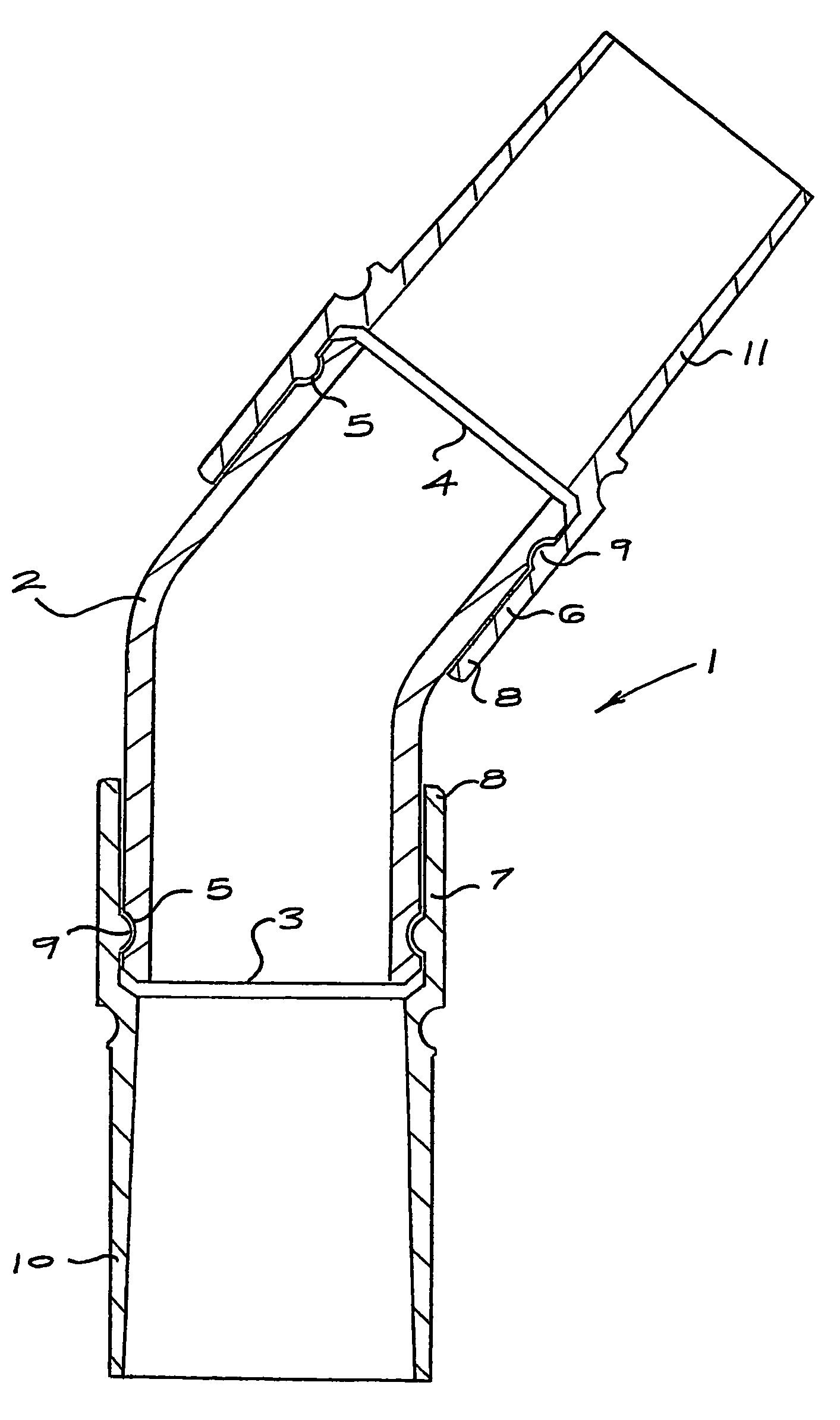
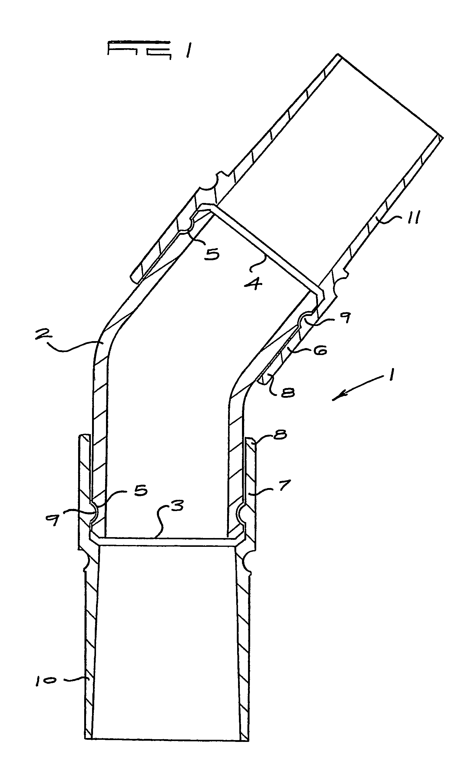
[0009]As illustrated the elbow joint (1) is suitable for connection between a swimming pool cleaner outlet and the inlet to a suction hose. Neither of these is shown and can be of any suitable known type.

[0010]The joint (1) comprises three components, an elbow (2), an inlet (3) and an outlet (4). These components (2), (3) and (4) will be moulded from suitable plastics material having a necessary degree of resilience to enable connection between the components to be snap fits.

[0011]Adjacent each end of the elbow (2) is a peripheral groove (5) and the set of the elbow ensures that the ends are inclined to each other at between 135° and 165°, preferably at 150°.

[0012]These ends of the elbow (2) form male components of swivel connections.

[0013]Each female component (6) and (7) has a cuff (8) to fit over an elbow end. Each cuff (8) has an internal circumferential rib (9) sized to engage by a snap fit into the appropriate groove (5) of an elbow and when the end is introduced into the cuff...


PUM


Abstract

A direction control means for apparatuses for cleaning submerged surfaces in the form of an elbow joint with swivel connections at each end. The connections may include anti-friction surfaces.

Description

FIELD OF THE INVENTION[0001]This invention relates to means for controlling the directional movement of automatic pool cleaners operating to clean submerged surfaces.BACKGROUND TO THE INVENTION[0002]Suction operated swimming pool cleaning devices are now well known. These pool cleaners are connected through a suction hose to the connection from the pool to the filtration plant. Many of these pool cleaners do not work satisfactorily in aboveground pools or in-ground pools having the bottom and sidewalls of the pool meeting at substantially right angles. The cleaners tend strongly to remain stationary in corners or alternatively to follow the join between bottom and sidewall of the pools. This problem can be overcome in some small measure by switching the pump motor off and on. This is not a satisfactory solution in that the directional control is insufficient to result in effective cleaning and the operation of the pool cleaner is no longer automatic.OBJECT OF THE INVENTION[0003]It i...

Claims


Application Information

Patent Timeline
Patent Type & Authority Patents(United States)
IPC IPC(8): F16L43/00F16L27/00A47L9/24E04H4/16F16L27/08
CPCA47L9/242E04H4/1636F16L27/0841
Inventor RISSIK, GEORGE VICTOR
Owner ARENGO 309
Learn More